Triguard SC300E MPP Processor Module (MPP) Issue 6 October 2005 Three MPPs are fitted in the three right hand slots of the main chassis. They provide a central processing facility for the Triguard SC300E system.
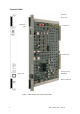
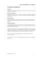
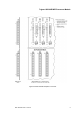
Triguard SC300E Switch S1 Switch S2 Diagnostic port Connector J1 Connector J2 Microprocessor 80486DX Keyswitch Back up batteries Figure 1-1 MPP General view and front panel detail 2 MPP October 2005 – Issue 6
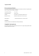
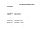
Triguard SC300E MPP Processor Module ASSOCIATED DOCUMENTATION Reference No Title 008-5097 Chassis User Manual 008-5105 MBB Bus Extender Module User Manual 008-5115 TBA Bus Expansion Adaptor User Manual 008-5217 TBT Bus Terminator User Manual SPECIFICATION Model MPP Processor Intel family EPROM 1 Mbyte fitted RAM 1 Mbyte fitted RAM backup battery (optional) Lithium battery, shelf life 8 to 10 years (program holdup 6 months) (Spares available) Inter processor communication Serial high
Triguard SC300E Environmental specifications The maximum ambient temperature measured at the hottest point within the Triguard system shall not be greater than 60 degrees centigrade. Temperature operating: +5°C to 60°C Temperature storage: -25°C to +70°C Humidity 5% to 95% non-condensing at ambient <40°C EMC/RFI Immunity Tested and certified to IEC 1131-Part 2 1994 Vibration/Shock Tested and certified to IEC 1131-Part 2 1994 Certification: General Certification: Ref.
Triguard SC300E MPP Processor Module TECHNICAL DESCRIPTION Physical The MPP is a 9U high PCB with integral front panel. Some aspects of MPP operation are determined by link settings. External connections Each module is plugged into the main chassis backplane bus system via two DIN41612 connectors J1 and J2 (Figure 1-1 ). Figure 2-1 shows the main chassis backplane bus interconnections. Diagnostic port A 9 -pin D-type connector is provided on the front panel. The pinout is listed in Table 2-4.
Triguard SC300E Connector summary Connector Location Type J3 (diagnosic port) MPP front panel (Figure 1-1) 9-pin D type socket female J1 (I/O bus) MPP rear edge (Figure 1-1) 96-pin DIN41612 type C male J2 (expansion bus) MPP rear edge (Figure 1-1) 96-pin DIN41612 type C male e (expansion bus) Rear of backplane (Figure2-1) 96-pin DIN41612 type C female f (watchdog) Rear of backplane 2-pin Combicon g (diagnosic) Rear of backplane 26-pin IDC socket CONTROLS AND INDICATORS Keyswitch User co
Triguard SC300E MPP Processor Module LED indicators The front panel LED’s illuminate to indicate the following conditions: RUN (green): MPP running (as indicated by microprocessor supervisory watchdog output) ON -LINE (yellow): MPP on line PROGRAM (yellow): MPP in program mode TEST (yellow): Reserved for future use HEALTH (green): Microprocessor running (as indicated by microprocessor address strobe monitoring circuit) I/O SCAN (yellow): Scan of I/O modules in progress BATTERY (green): Backup
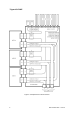
Triguard SC300E Figure 2-1 Backplane bus interconnections 8 MPP October 2005 – Issue 6
Triguard SC300E MPP Processor Module 0 1 2 3 UNIT ID 0 1 2 3 UNIT ID 0 1 2 3 UNIT ID Figure 2-2 MPP Related backplane connectors MPP October 2005 – Issue 6 9
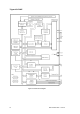
Triguard SC300E Figure 2-3 MPP Block diagram 10 MPP October 2005 – Issue 6
Triguard SC300E MPP Processor Module THEORY OF OPERATION SC300E system overview A block diagram showing the signal flow between the main functional areas of the MPP is shown in Figure 2-3 . External communication is via the chassis backplane wiring as summarised in Figure 2-1 . All SC300E input and output modules interface to three isolated I/O communications buses (shown collectively as the Processor-I/O Bus in Figure 2-1 ), each being controlled by one of the MPPs.
Triguard SC300E Commanded output states are received by an output module’s microcontrollers which, using 2-oo-3 hardware voters, set the outputs to the field.
Triguard SC300E MPP Processor Module configured I/O slots to determine their status. All I/O modules have identity type registers which allow the hot repair task to confirm the status of all fitted modules. Circuit details The block diagram (Figure 2-3 ) shows the main functional areas of the MPP circuit. Overall control of the circuit is by the microprocessor. At a lower level, individual parts of the circuit are controlled by Programmable logic (PALs) and peripheral devices. Power supplies The two 5.
Triguard SC300E Configuration registers The MPP is configured by setting 8-bit DIP switches S1 and S2 as listed in Table 2-3 and Table 2-4. Chassis address link settings The correct link combination for the main chassis is shown in Figure 2-5 . The physical locations of the chassis address setting links are indicated by small triangles in columns ‘b’ and ‘c’ of areas ‘d’ in Table 2-2. On the chassis backplane and in the links are identified as UNIT ID0 to UNIT ID3.
Triguard SC300E MPP Processor Module SUPPLEMENTARY INFORMATION Table 2-2.
Triguard SC300E Table 2-3. Configuration register switch settings for baud rate Switch position Baud rate S 1-7 957 Monitor Switch position S 2-5 S 2-6 Baud rate S 1-5 S- 1-6 S 2-7 CSI/O OFF OFF ON ON 1200 OFF ON ON 1200 ON ON ON 19200 (Default) ON ON ON 19200 NOTE The diagram below (Figure 2-6 ) shows S1 in its default condition, i.e. elements 3, 5, 6, 7 and 8 all ON (CLOSED), and, elements 1, 2 and 4 all OFF (OPEN). Figure 2-6 Switch S1 shown in Default condition Table 2-4.
Triguard SC300E MPP Processor Module Figure 2-7 Diagnostic port pinouts Table 2-5.
Triguard SC300E 18 MPP October 2005 – Issue 6
Triguard SC300E MPP Processor Module Figure 2-8 Rear backplane diagnostic port MPP October 2005 – Issue 6 19
Triguard SC300E SERVICING SCOPE The MPP is not field-repairable. Field servicing operations are confined to the routine replacement of SRAM backup batteries, and the total replacement of faulty MPPs. Spare keys are available. Faulty MPPs should be returned for repair. Before a spare MPP is fitted, ensure that both the positions of the links and the types of preprogrammed device are identical to those on the MPP that is being replaced.
Triguard SC300E MPP Processor Module The locations of the links are shown in general view showing link locations. Table 3-1.
Triguard SC300E REMOVAL AND REPLACEMENT Removal CAUTION To prevent battery drain in storage, the backup batteries fitted to new modules have insulation tabs fitted to their positive terminal. Remove these tabs before installing new modules. Ensure link LK14 to Position 2 to enable battery backup. The following applies to both faulty and non-faulty MPPs: 1. Turn the front panel keyswitch to RESET. 2. Remove the MPP. Replacement and warm start with two MPPs already running 1.
Triguard SC300E MPP Processor Module 6. The new MPP is on line when all three sets of MPP LEDs indicate the same.
Triguard SC300E BATTERY REPLACEMENT Fresh batteries will sustain SRAM for a total of about six months (either in one long stretch, or in several shorter stretches). The backup batteries should be replaced where it is known that the total battery drain period is approaching six months or once every five years (whichever occurs first). If the SC300E System is Operating 1. Remove one of the three MPPs. 2. Remove and safely dispose of both batteries. 3.
Triguard SC300E MPP Processor Module SERVICE SUPPORT SERVICE SUPPORT Spare parts and technical advice can be obtained from your local area offices. LIST OF SPARES Circuit ref Model No.