User Manual MP-Series Integrated Multi-axis Linear Stages Catalog Numbers MPMA-xABxxxx-S1C, MPMA-xACxxxx-S1C, MPMA-xAPxxxx-S1C, MPMA-xCBxxxx-S1C, MPMA-xCQxxxx-S1C, MPMA-xBExxxx-S2C, MPMA-xBIxxxx-S2C, MPMA-xBDxxxx-S2C
Important User Information Solid-state equipment has operational characteristics differing from those of electromechanical equipment. Safety Guidelines for the Application, Installation and Maintenance of Solid State Controls (publication SGI-1.1 available from your local Rockwell Automation sales office or online at http://www.rockwellautomation.com/literature/) describes some important differences between solid-state equipment and hard-wired electromechanical devices.
Table of Contents Preface About This Publication. . . . . . . . . . . . . . . . . . . . . . . . . . . . . . . . . . . . . . . . . . . . . 7 Who Should Use This Manual . . . . . . . . . . . . . . . . . . . . . . . . . . . . . . . . . . . . . . 7 Additional Resources . . . . . . . . . . . . . . . . . . . . . . . . . . . . . . . . . . . . . . . . . . . . . . . 7 Multi-axis Stage Safety Introduction. . . . . . . . . . . . . . . . . . . . . . . . . . . . . . . . . . . . . . . . . . . . . . . . . . . . . . .
Table of Contents Configuration Guidelines Introduction . . . . . . . . . . . . . . . . . . . . . . . . . . . . . . . . . . . . . . . . . . . . . . . . . . . . . Required Files . . . . . . . . . . . . . . . . . . . . . . . . . . . . . . . . . . . . . . . . . . . . . . . . . . . Configure Your Linear Stage . . . . . . . . . . . . . . . . . . . . . . . . . . . . . . . . . . . . . . Configure RSLogix 5000 Software for Linear Stages with Kinetix Multi-axis Drives . . . . . . . . . . . . . . . . . . . . . . .
Table of Contents PTC Thermal Signal . . . . . . . . . . . . . . . . . . . . . . . . . . . . . . . . . . . . . . . . 101 Certifications . . . . . . . . . . . . . . . . . . . . . . . . . . . . . . . . . . . . . . . . . . . . . . . 101 Accessories Introduction. . . . . . . . . . . . . . . . . . . . . . . . . . . . . . . . . . . . . . . . . . . . . . . . . . . . Interconnect Cables . . . . . . . . . . . . . . . . . . . . . . . . . . . . . . . . . . . . . . . . . . . . .
Table of Contents Notes: 6 Rockwell Automation Publication MPMA-UM001B-EN-P - November 2010
Preface Read this preface to familiarize yourself with the rest of the manual. About This Publication This manual provides detailed installation instructions for mounting, wiring, maintaining, and troubleshooting your MP-SeriesTM multi-axis integrated linear stage. For ease of use, going forward, when referring to the entire assembly, it may be called a multi-axis stage. Each axis of a multi-axis stage is a MP-Series integrated linear stage. When referring to single axis it will be called a linear stage.
Preface Resource Description CompactLogix SERCOS Interface Module Installation Instructions, publication 1768-IN005 Information on configuring and troubleshooting a CompactLogix motion module 16-Axis PCI SERCOS Interface Card Installation Instructions, publication 1784-IN041 SoftLogix SERCOS interface PCI card installation instructions SoftLogix Motion Card Setup and Configuration Manual, publication 1784-UM003 Information on configuring and troubleshooting your SoftLogix PCI card System Design for
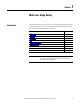
Chapter 1 Multi-axis Stage Safety Introduction This chapter describes the safety issues encountered while using multi-axis stages and the precautions you can take to minimize risk. Potential hazards discussed here are identified by labels affixed to the device.
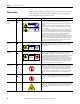
Chapter 1 Multi-axis Stage Safety Safety Labels Title Location Danger - Pinch Points and Heavy Object A To prevent injury and damage to the linear stage, review the safety labels and the details and location for each table before using the linear stage. The stages are shown individually and un-stacked for clarity.
Multi-axis Stage Safety Chapter 1 Figure 1 - Label Locations for Direct Drive Linear Stages A F E Product Nameplate ER DANG POINTS PINCHparts inside Moving /Tagout Lockout ZARD LIFT HA son Lift d Two Per require or car ry D M LOAG CANE Ca TETIC pan be D INFIE se cemaha THLD S ns iti ke rm IS AR ve rs fu eq an l to EA uipd ot me he nt r A N GE R ER DANG OUS HAZARDE VOLTAGAND LOCKOUTPOW ER TAGOUTSERVICING BEFORE C B F D Figure 2 - Label Locations for Ball Screw Linear Stages A D ER DANG POIN
Chapter 1 Multi-axis Stage Safety Clearances Install the multi-axis stage to avoid interference with the building, structures, utilities, other machines and equipment that may create a trapping hazard of pinch points. Dress cables using the Clearance Requirements on page 29 as a guide. Do not cross the path of motion or interfere with the cable carrier motion. General Safety Linear stages are capable of sudden and fast motion. Rockwell Automation, Inc.
Multi-axis Stage Safety Chapter 1 International Air Transport Association (IATA) Dangerous Goods Regulations. An IATA trained individual must be involved when shipping this product via domestic or international air freight. Packing Instruction 902 provides information regarding the preparation of this product for air transportation.
Chapter 1 Multi-axis Stage Safety Notes: 14 Rockwell Automation Publication MPMA-UM001B-EN-P - November 2010
Chapter 2 Understanding Your Multi-axis Stage Introduction Use this chapter to become familiar with the multi-axis stage components, its maintenance needs, and its configuration.
Chapter 2 Understanding Your Multi-axis Stage Identifying Your Multi-axis Stage MPMA - xxxxxxxxx - xxx Your multi-axis stage is constructed using linear stages and a cable carrier module assembly. Use the following key to identify your multi-axis stage and its options. For details on an individual stages refer to Identifying the Individual Linear Stages in Your Multi-axis Stage.
Understanding Your Multi-axis Stage Identifying the Components of Your Multi-axis Stage Chapter 2 Use the diagrams and descriptions to identify the unique components of the multi-axis stage then refer to Identifying the Components of Each Linear Stage for details of the each linear stage component.
Chapter 2 Understanding Your Multi-axis Stage Figure 4 - Components of XZ Center Stacked Multi-axis Stage (MPMA-xBxxxxxx-SxC shown) Z-Axis X-Axis 6 Refer to Component Descriptions beginning on page 23 for the name and description of each numbered item.
Understanding Your Multi-axis Stage Chapter 2 Figure 5 - Components of XY Cantilevered Stacked (Left Side Cantilever) Multi-axis Stages (MPMA- xCxxxxxxx-SxC shown) 6 Y-Axis X- Axis Refer to Component Descriptions beginning on page 23 for the name and description of each numbered item.
Chapter 2 Understanding Your Multi-axis Stage Identifying the Individual Linear Stages in Your Multi-axis Stage Use the following key to identify each linear stage and its options. MPAS - x x xxx x - x xx x x x Cable X = Cable carrier module identified at multi-axis level Brake 2 = No brake 4 = 24V DC brake Cover S = Covered with strip seals (IP30 protection) Screw Lead/Direct Drive 20 = 20.0 mm/rev (0.79 in.
Understanding Your Multi-axis Stage Chapter 2 Figure 6 - Components of the Direct Drive Linear Stage (MPAS-xxxxxxx-ALMx2x) 4 3 9 (4x) 2 (4x) 7 (2x) 5 (2x) 6 8 (4x) 1 14 15 10 11 12 (4x) 13 (2x) Refer to Component Descriptions beginning on page 23 for the name and description of each numbered item.
Chapter 2 Understanding Your Multi-axis Stage Figure 7 - Components of the Ball Screw Linear Stage (MPAS-xxxxxx-VxxSxx) 4 3 9 (4x) 2 (4) 5 (2) 7 (2) 19 8 (4) 20 1 12 (4) 13 (2) 18 17 21 (2) 16 Refer to Component Descriptions beginning on page 23 for the name and description of each numbered item.
Understanding Your Multi-axis Stage Chapter 2 Component Descriptions Component Number Component Description 1 Ground Screw and Ground Label Use the labeled M5 x 0.8 - 6H ground screw to connect the linear stage to a facility safety ground. 2 Bearing Lubrication Ports These capped ports provide access to the linear bearings without dismantling the linear stage. 3 Carriage This is where your load mounts. The carriage has mounting holes and pilot guide holes.
Chapter 2 Understanding Your Multi-axis Stage Maintenance Intervals This section lists typical maintenance intervals for your linear stage, and references the section where maintenance procedures are described. IMPORTANT The suggested time period for re-lubrication is only a starting point. You should determine the frequency of re-lubrication that is best suited to your application as an application's environment, motion profile, and duty cycle can effect the re-lubrication time period required.
Chapter 3 Planning a Multi-axis Stage Installation Introduction Use this chapter to establish a suitable environment and physical location for your multi-axis stage. Topic Page General Safety Standards for Multi-axis Stage Installations 25 UL Safety Standards for Linear Stage Installations 26 Mounting Restrictions 27 Environmental Factors 27 Clearance Requirements 29 Requirements to be met when mounting your multi-axis stage include the following.
Chapter 3 Planning a Multi-axis Stage Installation UL Safety Standards for Linear Stage Installations All linear stage installations should follow Underwriters Laboratories standard UL 1740 - Standard for Safety for Robots and Robotic Equipment. UL 1740 covers robots and robotic equipment rated at 600V or less and intended for installation in accordance with the National Electrical Code, ANSI/NFPA 70.
Planning a Multi-axis Stage Installation Chapter 3 Mounting Restrictions When locating your multi-axis stage include the following: · Environmental Factors · Mounting Surface Restrictions · Mounting Orientations for Center and Cantilever Multi-axis Stage XY (MPMA-xA/Cxxxxxx-SxC) · Mounting Orientations for Center Stacked XZ Multi-axis Stage (MPMAxBxxxxxx-SxC) · Clearance Requirements Environmental Factors Factor Applicability Temperature The linear stage does not require any special cooling considerat
Chapter 3 Planning a Multi-axis Stage Installation Mounting Orientations for Center and Cantilever Multi-axis Stage XY (MPMA-xA/Cxxxxxx-SxC) Mounting Orientation Restriction Ceiling - inverted surface A ceiling mount (inverted on a horizontal surface) is not recommended. Stages mounted in this orientation are subject to premature cable carrier failure. Wall - horizontal vertical or incline Use only center stacked XZ multi-axis stage for wall mounting applications.
Planning a Multi-axis Stage Installation Chapter 3 Clearance Requirements The figures depict the minimum clearances for each multi-axis stage type. Power and feedback cables may impose additional clearance requirements. Refer to Interconnect Cables on page 103 for connector and bend radius requirements. Figure 8 - Minimum Clearance Requirements MPMA-xBxxxxxx-SxC Additional Clearance Is Required for Power and Feedback Cables. 3.2 mm (0.125 in.
Chapter 3 Planning a Multi-axis Stage Installation Notes: 30 Rockwell Automation Publication MPMA-UM001B-EN-P - November 2010
Chapter 4 Mounting and Connecting the MP-Series Integrated Multi-axis Linear Stage Introduction This chapter provides unpacking, handling, and mounting instructions.
Chapter 4 Mounting and Connecting the MP-Series Integrated Multi-axis Linear Stage Be sure the information listed on the purchase order correlates to the information on the packing slip for your linear stage and its accessories. Inspect the assemblies and confirm, if applicable, the presence of specified options. ATTENTION: Direct drive linear stages contain powerful permanent magnets that require extreme caution during handling. Do not disassemble the linear stage.
Mounting and Connecting the MP-Series Integrated Multi-axis Linear Stage Chapter 4 Unpack the Multi-axis Stage ATTENTION: Improper handling of a multi-axis stage can cause personal injury and damage to the equipment. Follow these unpacking instruction to safely unpack and avoid damaging your multi-axis stage. The following procedure show you how to safely remove the stack stage from its shipping crate. 1. Remove the crate cover and baces. 2. Attach lifting straps to shipping platform eyebolts.
Chapter 4 Mounting and Connecting the MP-Series Integrated Multi-axis Linear Stage 4. Support cantilevered or secondary stage while removing crate shipping platform. ATTENTION: Never use lifting straps to move the multi-axis stage. Using lifting straps will deform covers and strip seals. Always use a three-person lift to move the multi-axis stage. Use a three-person lift to move the multi-axis stage. Three-Person Lift - One person at each end of base stage grasping the bottom of the stage near the ends.
Mounting and Connecting the MP-Series Integrated Multi-axis Linear Stage Chapter 4 Store Packaging Material Keep the crate and packing materials in case the multi-axis stage needs to be returned for warranty service or stored for an extended period of time. 1. Tape screws and clamp hardware to the plywood board brace. 2. Put the end caps and braces in their original positions and place all packing material inside the crate.
Chapter 4 Mounting and Connecting the MP-Series Integrated Multi-axis Linear Stage 1. Be sure the mounting surface is clear of any and all foreign material. IMPORTANT Do not use abrasives to clean the surface. If necessary, stone the mounting surface (acetone or methanol may be applied as cleaning agent). 2. Verify the flatness of the surface to which the linear stage is to be mounted. The total indicator reading (TIR) is 0.0254 mm (0.001 in.) per 300 mm (12 in.).
Mounting and Connecting the MP-Series Integrated Multi-axis Linear Stage Connect the Multi-axis Stage Chapter 4 The installation procedure assumes you have prepared your system for correct electrical bonding and understand the importance of electrical bonding for correct operation of the system to which your linear stage belongs. If you are unfamiliar with electrical bonding, the section Attach the Ground Strap and Interface Cables briefly describes and illustrates correct system grounding techniques.
Chapter 4 Mounting and Connecting the MP-Series Integrated Multi-axis Linear Stage 2. Torque the ground screw at the lower stage to 2 N•m (18 lb•in.). M5 x 0.8 -6H Ground Screw Lug Braided Ground Wire 12 mm (0.5 in.) min. 3. Form a drip loop in each cable at a point directly before it attaches to the motor.
Chapter 4 Mounting and Connecting the MP-Series Integrated Multi-axis Linear Stage OR Y-Axis (or Z-Axis) Power and Feedback Cables Lables Cable Drip Loop X-Axis Power and Feedback Cables Lables Align flat surfaces 4. Identify the multi-axis stage power and feedback cables by the labels near the connector. 5. Attach the feedback cable, and the combination power and brake cable to the motor.
Chapter 4 Mounting and Connecting the MP-Series Integrated Multi-axis Linear Stage c. Hand tighten the knurled collar five to six turns to fully seat each connector. ATTENTION: Keyed connectors must be properly aligned and hand-tightened the recommended number of turns. Improper alignment is indicated by the need for excessive force, such as the use of tools, to fully seat connectors. Connectors must be fully tightened for connector seals to be effective.
Chapter 4 Mounting and Connecting the MP-Series Integrated Multi-axis Linear Stage Meeting UL Installation Standards Multi-axis stage installations should follow Underwriters Laboratories standard UL 1740 - Standard for Safety for Robots and Robotic Equipment. Refer to UL Safety Standards for Linear Stage Installations on page 26 for a brief description of this standard. ATTENTION: UL 1740 requires all linear stage installations be equipped as described below.
Chapter 4 Mounting and Connecting the MP-Series Integrated Multi-axis Linear Stage Notes: 42 Rockwell Automation Publication MPMA-UM001B-EN-P - November 2010
Chapter 5 Linear Stage Connector Data Introduction This chapter provides power and feedback cable information for the linear stage. Linear Stage Power and Feedback Connections Topic Page Linear Stage Power and Feedback Connections 43 The following tables identify the power and feedback pinouts for circular connectors for used with standard Allen-Bradley cables. The direct drive and ball screw linear stages use different encoder types.
Chapter 5 Linear Stage Connector Data Table 2 - Feedback Connector for Direct Drive Linear Stage Pin Signal Name Wire Color (2) Signal Description 1 AM+ Yellow A Quad B TTL - A Differential 2 AM- White/yellow A Quad B TTL - A Differential 3 BM+ Brown A Quad B TTL - B Differential 4 BM- White/Brown A Quad B TTL -B Differential 5 IM+ Violet TTL - Index Mark Differential 6 IM- White/Violet TTL - Index Mark Differential 7 Reserved – – 9 +5V DC White/Red Encoder and Hall Sens
Linear Stage Connector Data Chapter 5 Table 3 - Feedback Connector for Ball Screw Linear Stage Pin Signal Name MPAS- Signal Description Axxxxx (230V) Signal Name MPASBxxxxx (460V) 1 Sin+ Analog Differential 1V p-p Sin+ 2 Sin- Analog Differential 1V p-p Sin- 3 Cos+ Analog Differential 1V p-p Cos+ 4 Cos- Analog Differential 1V p-p Data- 5 Data+ Serial Data Differential Signal + Data+ 6 Data- Serial Data Differential Signal - Data- 7 Reserved – Reserved 9 +5V DC 230V MPAS Enc
Chapter 5 Linear Stage Connector Data Notes: 46 Rockwell Automation Publication MPMA-UM001B-EN-P - November 2010
Chapter 6 Configuration Guidelines Introduction Required Files Your multi-axis stage is made from individual MP-Series Integrated Linear Stages. This chapter provides guidelines for using RSLogix 5000 software to configure a servo drive system with an Allen-Bradley MP-Series linear stage. Use this section to configure the individual stages.
Chapter 6 Configuration Guidelines Configure Your Linear Stage Configure the linear stage by using the parameter settings described in this chapter. ATTENTION: Moving parts can injure. Before running the stage, make sure all components are secure. Check that the linear stage is clear of foreign matter and tools. Objects hit by the moving stage can cause personnel injury or damage to the equipment. Incorrect motor, Hall, or encoder wiring can cause uncontrolled motion.
Configuration Guidelines Configure RSLogix 5000 Software for Linear Stages with Kinetix Multi-axis Drives Chapter 6 The RSLogix 5000 software parameters provide here are for basic setup and tuning parameters of MP-Series Integrated Linear Stages. • In Set Axis Properties in RSLogix Software the drive parameters tables for direct drive and ball screw drive linear stage are shown.
Chapter 6 Configuration Guidelines Axis Properties Tab Parameter Entry/Selection, with applicable distance unit settings Metric Conversion Hookup (1) English Positioning Mode Linear Conversion Constant 200 drive counts / 1.0 mm 5080 drive counts / 1.0 in. Test Increment 70 mm, min for Ultra3000 drive 20 mm Kinetix 2000 drive 20 mm Kinetix 6000 drive 2.76 in. min for Ultra3000 drive 0.787 in. Kinetix 2000 drive 0.787 in.
Configuration Guidelines Chapter 6 Ball Screw Drive Stages Enter these parameters in the Axis Properties tab of RSLogix 5000 software for ball screw linear stages, catalog number MPAS-xxxxxx-Vxxxxx.
Chapter 6 Configuration Guidelines Axis Properties Tab Parameter Entry/Selection, with applicable distance unit settings Metric Limits English Hard Travel Limits Check if hardware limits are in use.
Configuration Guidelines Chapter 6 Tuning Linear Stages with RSLogix 5000 Software This section shows the steps to tune linear stages with RSLogix 5000 software, version 16.xx. IMPORTANT ATTENTION: The Tuning and Loop Gain procedures apply only to the ball screw linear stages. The Travel Limit procedures apply to direct drive and ball screw linear stages. • Tuning your linear stage requires you to calculate and configure the loop gain based on the actual measured inertia.
Chapter 6 Configuration Guidelines 3. Reduce the default Stopping Time Limit from 10 seconds to 0.5 seconds. IMPORTANT To prevent the carriage from moving, or falling when installed in a vertical orientation, the Stopping Time Limit must be set to 0.99 seconds or less. 4. Select the Tune tab in the Axis Properties dialog box and enter the following parameters: • Travel Limit. Set to a maximum of the travel length of the linear stage. • Speed (velocity). • Torque/Force.
Configuration Guidelines Chapter 6 6. Click Yes to begin tuning the linear stage. ATTENTION: Motion occurs immediately after clicking Yes. Tuning is complete when the Tune Servo dialog box appears.
Chapter 6 Configuration Guidelines 7. Select Yes to exit Tuning, and display the Tune Results dialog box. Calculate and Configure the Loop Gain IMPORTANT These Loop Gain procedures apply only to ball screw linear stages. You must calculate a position loop bandwidth based on the actual measured inertia. This is with the values from the Tune Results dialog box for a ball screw drive linear stage. The Tune Results dialog box above shows a default Position Loop Bandwidth of 45.
Configuration Guidelines Chapter 6 2. Enter the Corrected Position Bandwidth value 5.73532 as the Position Loop Bandwidth and click OK. 3. Answer the remaining dialog boxes to apply the values. The proper Position Bandwidth results in a stable starting point, from which you may adjust the gains to fit the application requirements.
Chapter 6 Configuration Guidelines Configure Ultraware Software for Linear Stages with Ultra3000 Drives The following steps assume that the MP-Series linear stage and an Ultra3000 drive are installed and wired as one axis of a motion system. 1. Connect a serial cable model, catalog number 2090-DAPC-D09xx, to the CN3 connector on your Ultra3000 drive. 2. Apply AC input power to the Ultra3000 drive. 3.
Configuration Guidelines Chapter 6 7. In the Motor Encoder Units pull-down menu, enter the appropriate values from the tables on page 59. Velocity, position, and acceleration counts per unit are based on the selected User Units (mm or in.). User Unit Scaling Parameters (1) Distance Units for Ball Screw Linear Stages Metric English MPAS-xxxxxx-V20xxx MPAS-xxxxxx-V20xxx Velocity Label mm/s in./s Velocity Scale 6553.6 166461.44 Position Label mm in. Position Scale 6553.6 166461.
Chapter 6 Configuration Guidelines Set Travel Limits MP-Series Integrated Linear Stages are designed to use the software overtravel limits available in RSLogix 5000 and Ultraware software. IMPORTANT Travel Limits apply to direct drive and ball screw linear stages. Set Overtravel limits according to the maximum speed of the servo drive system and the payload of the application.
Chapter 7 Maintenance Introduction This chapter describes the maintenance procedures for your linear stage. Topic Page Before You Begin 61 Recommended Maintenance Intervals 61 Lubricate the Bearing 62 Clean the Strip Seal 63 Clean the Cover 63 IMPORTANT Before You Begin Any person that teaches, operates, maintains, or repairs these linear stages must be trained and demonstrate the competence to safely perform the assigned task.
Chapter 7 Maintenance Lubricate the Bearing Lubricate the linear stage bearings as shown and described below. Use the MPSeries Integrated Linear Stage grease pump kit, and additional grease cartridges as necessary. Figure 11 - Direct Drive Linear Stage Lubrication Bearing Lubrication Ports (two per end cap) Figure 12 - Ball Screw Linear Stage Lubrication Ball Nut Lubrication Port (one per linear stage) Bearing Lubrication Ports (two per end cap) 1.
Maintenance Chapter 7 5. Repeat step 3 and step 4 to the other lubrication ports. 6. Move the carriage to opposite end of travel and repeat steps 1…5. 7. Remove the clamp. 8. Reinstall the protective caps on all the lubrication ports. Clean the Strip Seal Clean the strip seals, if installed, using a lint free cloth lightly saturated with isopropyl alcohol. IMPORTANT Replace the strip seal if it cannot be cleaned, or if an uneven or scored surface is detected during cleaning.
Chapter 7 Maintenance Notes: 64 Rockwell Automation Publication MPMA-UM001B-EN-P - November 2010
Chapter 8 Removing and Replacing Multi-axis Stage Components Introduction This chapter provides procedures for user-replaceable parts on the multi-axis stage. Procedures for the cover, and the rotary motor replacement are limited to the secondary stage. Return your multi-axis stage to factory for the cover and the rotary motor replacement for the base stage.
Chapter 8 Removing and Replacing Multi-axis Stage Components Before You Begin Assemble these tools before you begin removal and replacement procedures. • Torque wrench • 2.5 mm, 3 mm, 4 mm, 5 mm, and 6mm L-shaped hex keys • 0.8 mm (0.030 in.) shim • Tin snips • Loctite 222 • Phillips and flat-blade screwdrivers • Ruler • Pencil or marker Cable Carrier Assembly Removal Procedures There are three different cable carrier removal procedures.
Removing and Replacing Multi-axis Stage Components Chapter 8 Remove the Cable Carrier Assembly For MPMA-xxDxxxxxx-SxC and MPMA-xxExxxxxx-SxC Multi-axis Stages Follow this procedure is to remove the cable carrier assembly from multi-axis stage with a direct drive base axis and ballscrew secondary axis. TIP Mark the location of the end brackets before removing the cable carrier, this will make it easier to align it when reinstalling. 1.
Chapter 8 Removing and Replacing Multi-axis Stage Components 1. Remove and save for re-installation any P-clamps and hardware used to route cables from upper axis to lower axis. 2. Disconnect the motor power connector from the upper axis motor. 3. Disconnect the feedback connector from the upper axis motor. 4. Remove the two socket head cap screws (SHCS) that attach the cable carrier angle bracket to the underside of the lower carriage. 5.
Removing and Replacing Multi-axis Stage Components Chapter 8 10. Slide the screws out of the bracket slots and lay carrier parallel to lower stage. 11. Repeat step 3 through 10 for the base stage. Cable Carrier Assembly Installation Follow the Cable Carrier Assembly Removal procedure for your multi-axis stage in reverse adding the following steps when needed: • Align the cable carrier using the alignment marks made when the worn cable carrier was removed.
Chapter 8 Removing and Replacing Multi-axis Stage Components Remove the Cover Follow these directions to remove a secondary stage cover. 1. Remove strip seals following the strip seal removal procedure. 2. Remove the four M4 screws securing the linear stage cover to the end caps. 3. Remove the cover. M4 SHCS (2 per side) Install the Cover Follow these directions to install a secondary stage cover. 1.
Removing and Replacing Multi-axis Stage Components Replace the Strip Seal Chapter 8 Follow these directions to replace the strip seals. ATTENTION: Handle strip seal material with care. The strip seal has sharp edges that can cause personal injury if mishandled. 1. Remove power from the linear stage, and lock out and tag the power source. 2. Follow the instructions below on how to measure, mark, and cut new strip seals. 1) Mark needed strip length. 3) Make two 45° marks to centerline.
Chapter 8 Removing and Replacing Multi-axis Stage Components 13. Adjust the seal guide by inserting a 0.8 mm (0.030 in.) shim between the seal guide and the strip seal. Strip Seal 0.8 mm (0.03 in.) Shim Seal Guide 14. Return the linear stage to service. Install the Side Cover Follow these directions to install a side cover. 1.
Removing and Replacing Multi-axis Stage Components Replace the Rotary Motor Chapter 8 Follow these directions to replace a secondary stage rotary motor. 1. Disconnect the motor cables. 2. Remove the four M5 SHCS and lock washers that secure the motor to the linear stage. M5 SHCS (4x) M4 SHCS B A 3. Remove the motor. IMPORTANT Measure the position of the coupling on the motor shaft as shown in panel B of the diagram above. 4. Mark the measured coupling position on the new motor shaft. 5.
Chapter 8 Removing and Replacing Multi-axis Stage Components 10. Attach the power and feedback cables to the motor, by aligning the flat edges on the cable connector with that on the motor connector.
Chapter 9 Troubleshooting Introduction This chapter is divided into three sections. The first section provides diagnostic tables to use only during axis commissioning. Use the operational section to troubleshoot either a direct drive or ball screw linear stage after the axis is up and running, and use the thermistor measurement section only when direct drive operational troubleshooting suggests it.
Chapter 9 Troubleshooting Troubleshooting During Commission and Startup Use this section to diagnose and correct troubles encountered while using RSLogix 5000 software to commission and startup your linear stage. Description Possible Cause Corrective Action Initialization stops at SERCOS Level 3 and Logix software reports Motor Attribute Error. Incorrect motor catalog number. Enter correct motor catalog number. Incorrect drive firmware.
Troubleshooting Chapter 9 Evaluate the Direct Drive Linear Stage 1. Power down the drive system. 2. Disconnect the drive from the linear stage. ATTENTION: Lockout and tagout input power before servicing the linear stage. 3. By hand move the carriage through the entire range of motion. It should move free and smooth. 4. If excessive resistance is felt, clean and relubricate the linear bearings. 5. Perform the procedures for a direct drive linear stage listed in the troubleshooting tables on page 78. 6.
Chapter 9 Troubleshooting 5. If excessive resistance is felt, clean and relubricate the linear bearings. 6. Perform the procedures for a ball screw linear stage listed in the troubleshooting tables on page 78 and page 79. If the problem persists, return for factory evaluation and possible repair. Table 6 - Troubleshooting Procedures for Direct Drive or Ball Screw Linear Stages ATTENTION: Lockout and tagout input power before servicing the linear stage.
Troubleshooting Chapter 9 Description Possible Cause Corrective Action Drive reporting error E07 or E20. Environment is electrically noisy and cable shield is compromised. Verify carrier cable module and extension cable shield termination are secure. Drive reporting error E05. Defective motor Disconnect the flex cable and probe the Motor Power connector (white Mate-N-Lok) in the open Junction Box. 1.
Chapter 9 Troubleshooting Notes: 80 Rockwell Automation Publication MPMA-UM001B-EN-P - November 2010
Appendix A Specifications and Dimensions This appendix is a supplement to this document. Associated Kinetix publications listed in Additional Resources on page 7 and information in product specifications may supersede the information in this appendix.
Appendix A Specifications and Dimensions MPMA-xABxxxxxx-xxx Product Specifications and Dimensions These specifications apply to Center Stacked X/Y stages with 250 mm frame linear motor driven X-axis and 200 mm frame linear motor driven Y-axis. Maximum payload is 15 kg (33.1 lb). For heavier loads, contact your Rockwell Automation sales representative. Table 9 - MPMA-xABxxxxxx-xxx Product Specifications Multi-axis Linear Stage Cat. No. Travel mm (in.) X-axis Y-axis MPMA-xABC0C0A0-S1C 200 (7.
Specifications and Dimensions Appendix A Table 11 - MPMA-xABxxxxxx-xxx Product Dimensions 232 (9.13) TL/2 25.4 (1.00) Bumper Travel TL/2 215.7 (8.49) 25.4 (1.00) Bumper Travel 25.4 (1.00) Bumper Travel 53.6 (2.11) TU/2 See Detail A 65.4 (2.58) 130.8 (5.15) Base 248.7 (9.79) 86.1 (3.39) 339 (13.35) Carriage Base 172.2 (6.78) B 104.1 (4.10) 117.7 (4.63) TU/2 (4X) M8 X 1.25-6H 12.0 (0.47) (4X) Ø 6.8 (0.27) 45.4 (1.79) Thru Secondary 3.35 (0.132) Dimensions are in mm (in.
Appendix A Specifications and Dimensions MPMA-xACxxxxxx-xxx Product Specifications and Dimensions These specifications apply to Center Stacked X/Y stages with 250 mm frame linear motor driven X-axis and 250 mm frame linear motor driven Y-axis. Maximum payload is 20 kg (44.0 lb). For heavier loads, contact your Rockwell Automation sales representative. Table 13 - MPMA-xACxxxxxx-xxx Product Specifications Travel mm (in.) Multi-axis Linear Stage Cat. No.
Specifications and Dimensions Appendix A Table 15 - MPMA-xACxxxxxx-xxx Product Dimensions 281 (11.06) TL/2 25.4 (1.00) Bumper Travel TL/2 264.7 (10.42) 25.4 (1.00) Bumper Travel 25.4 (1.00) Bumper Travel 53.5 (2.11) TU/2 (4X) M8 X 1.25-6H 12.0 (0.47) (4X) Ø 6.8 (0.27) 45.4 (1.79) Thru See Detail A 65.4 (2.57) 339 (13.35) Carriage 130.8 (5.15) Base 86.1 (3.39) Base B 248.7 (9.79) 172.2 (6.78) 104.1 (4.10) 117.7 (4.63) TU/2 Dimensions are in mm (in.
Appendix A Specifications and Dimensions MPMA-xAPxxxxxx-xxx Product Specifications and Dimensions These specifications apply to Center Stacked X/Y stages with 200 mm frame ballscrew driven X-axis and 200 mm frame ballscrew driven Y-axis. Maximum payload is 20 kg (44.0 lb). For heavier loads, contact your Rockwell Automation sales representative. Table 17 - MPMA-xAPxxxxxx-xxx Product Specifications Travel mm (in.) Multi-axis Linear Stage Cat. No.
Specifications and Dimensions Appendix A Table 19 - MPMA-xAPxxxxxx-xxx Product Dimensions 232 (9.13) 25.4 (1.00) Bumper Travel TL/2 TL/2 215.7 (8.49) 25.4 (1.00) Bumper Travel (4X) M10 x 1.5-6H Thru (2 per end cap) Access point for linear bearing lubrication. 25.4 (1.00) Bumper Travel Ø13.0 (0.5) Access point for ballscrew nut lubrication. TU/2 44.2 (1.74) 75.3 (2.97) See Detail A 61.5 (2.42) B 130.8 Base (5.15) 239 (9.4) Carriage Base 130.8 (5.15) 199.7 (7.86) 69.7 (2.
Appendix A Specifications and Dimensions Table 20 - MPMA-xAPxxxxxx-xxx Dimensions A Stage Length (X-axis) TL Travel (X-axis) B Stage Length (Y-axis) TU Travel (Y-axis) C Mounting Locations (X-axis) mm (in.) mm (in.) mm (in.) mm (in.) Qty MPMA-AAPB8B8A0-S1C 521 (20.5) 180 (7.1) 521 (20.5) 180 (7.1) 8 MPMA-AAPC4C4A0-S1C 581 (22.9) 240 (9.4) 581 (22.9) 240 (9.4) MPMA-AAPD0D0A0-S1C 641 (25.2) 300 (11.8) 641 (25.2) 300 (11.8) MPMA-AAPE2E2A0-S1C 761 (30.0) 420 (16.5) 761 (30.
Specifications and Dimensions MPMA-xCBxxxxxx-xxx Product Specifications and Dimensions Appendix A These specifications apply to Cartesian Stacked X/Y stages with 250 mm frame linear motor driven X-axis and 200 mm frame linear motor driven Y-axis. Maximum payload is 20 kg (44.0 lb). For heavier loads, contact your Rockwell Automation sales representative. Table 21 - MPMA-xCBxxxxxx-xxx Product Specifications Travel mm (in.) Multi-axis Linear Stage Cat. No. X-axis MPMA-xCBD2D2A0-S1C 320 (12.
Appendix A Specifications and Dimensions Table 23 - MPMA-xCBxxxxxx-xxx Product Dimensions TL/2 25.4 (1.00) Bumper Travel (4X) M8 X 1.25-6H 12.0 (0.47) (4X) Ø 6.8 (0.27) 45.1 (1.77) Thru TL/2 25.4 (1.00) Bumper Travel TU/2 (4X) 9/16-12 UNC Thru (2 per end cap) Access point for linear bearing lubrication. 104.1 (4.10) Secondary 130.8 (5.15) See Detail A 248.7 (9.79) 172.2 Base (6.78) B Secondary 339 (13.3) Carriage 198 (7.8) 86.1 (3.39) 117.7 (4.63) 215.7 (8.49) 121.9 (4.80) 232 (9.
Specifications and Dimensions Appendix A Table 24 - MPMA-xCBxxxxxx-xxx Dimensions A Stage Length (X-axis) TL Travel (X-axis) B Stage Length (Y-axis) TU Travel (Y-axis) C Mounting Locations (X-axis) mm (in.) mm (in.) mm (in.) mm (in.) Qty 761 (30.0) 320 (12.6) 761 (30.0) 320 (12.6) 881 (34.7) 440 (17.3) 1001 (39.4) 560 (22.0) 1121 (44.1) 680 (26.8) MPMA-ACBI0F6A0-S1C 1241 (48.9) 800 (31.5) MPMA-ACBJ2F6A0-S1C 1361 (53.6) 920 (36.2) MPMA-BCBD2D2A0-S1C 761 (30.0) 320 (12.
Appendix A Specifications and Dimensions MPMA-xCQxxxxxx-xxx Product Specifications and Dimensions These specifications apply to Cartesian Stacked X/Y stages with 250 mm frame ballscrew driven X-axis and 200 mm frame ballscrew driven Y-axis. Maximum payload is 25 kg (55.1 lb). For heavier loads, contact your Rockwell Automation sales representative. Table 25 - MPMA-xCQxxxxxx-xxx Product Specifications Travel mm (in.) Multi-axis Linear Stage Cat. No. X-axis MPMA-xCQD0D0A0-S1C 300 (11.
Specifications and Dimensions Appendix A Table 27 - MPMA-xCQxxxxxx-xxx Product Dimensions 25.4 (1.00) Bumper Travel 25.4 (1.00) Bumper Travel (4X) M8 X 1.25-6H 12.0 (0.47) (4X) Ø 6.8 (0.27) 45.1 (1.77) Thru Mounting holes are not centered on carriage. (4X) 9/16-12 UNC Thru (2 per end cap) Access point for linear bearing lubrication. TL/2 TL/2 25.4 (1.00) Bumper Travel TU/2 44.2 (1.74) 75.3 239 (2.96) 130.8 (9.4) 239 (5.15) (9.4) Carriage Secondary B Secondary 298.7 (11.
Appendix A Specifications and Dimensions MPMA-xBExxxxxx-xxx Product Specifications and Dimensions These specifications apply to Center Stacked X/Z stages with 200 mm frame linear motor driven X-axis and 150 mm frame ballscrew driven Z-axis. Maximum payload is 20 kg (44.0 lb). For heavier loads, contact your Rockwell Automation sales representative. Table 29 - MPMA-xBExxxxxx-xxx Product Specifications Travel mm (in.) Bi-directional Repeatability (µm) Encoder Type Multi-axis Linear Stage Cat. No.
Specifications and Dimensions Appendix A Table 31 - MPMA-xBExxxxxx-xxx Product Dimensions 181.5 (7.15) TL/2 25.4 (1.00) Bumper Travel TL/2 30.0 (1.18) Bumper Travel 25.4 (1.00) Bumper Travel 165 (6.5) (4X) Ø 7.00 (0.276) Thru 65.0 (2.56) 62.15 (2.45) B 239 (9.4) Carriage 165 (6.5) Base See Detail A TU/2 82.5 (3.25) Base 130.8 (5.15) 130 (5.12) 117.7 (4.63) TU/2 (4X) M10 x 1.25 Thru (2 per end cap) Access point for linear bearing lubrication. (4X) M8 X 1.25-6H 12.0 (0.47) 163.1 (6.
Appendix A Specifications and Dimensions MPMA-xBIxxxxxx-xxx Product Specifications and Dimensions These specifications apply to Center Stacked X/Z stages with 200 mm frame ballscrew driven X-axis and 150 mm frame ballscrew driven Z-axis. Maximum payload is 25 kg (55.1 lb). For heavier loads, contact your Rockwell Automation sales representative. Table 33 - MPMA-xBIxxxxxx-xxx Product Specifications Travel mm (in.) Multi-axis Linear Stage Cat. No.
Specifications and Dimensions Appendix A Table 35 - MPMA-xBIxxxxxx-xxx Product Dimensions 25.4 (1.00) Bumper Travel 181.5 (7.15) 165 (6.5) TL/2 TL/2 37.0 (1.46) (4X) Ø7.00 (0.276) Thru 65.0 (2.56) Base (4X) M10 x 1.25 Thru (2 per end cap) Access point for linear bearing lubrication. 30.0 (1.18) Bumper Travel 25.4 (1.00) Bumper Travel Ø13.0 (0.5) Access point for ballscrew nut lubrication. TU/2 82.5 (3.25) 62.1 (2.45) B 239 (9.4) Carriage 165 (6.5) Base 130.8 (5.15) 199.7 (7.86) 130 (5.
Appendix A Specifications and Dimensions MPMA-xBDxxxxxx-xxx Product Specifications and Dimensions These specifications apply to Center Stacked X/Z stages with 250 mm frame linear motor driven X-axis and 150 mm frame ballscrew driven Z-axis. Maximum payload is 20 kg (44.0 lb). For heavier loads, contact your Rockwell Automation sales representative. Table 37 - MPMA-xBDxxxxxx-xxx Product Specifications Travel mm (in.) Bi-directional Repeatability (µm) Encoder Type Multi-axis Linear Stage Cat. No.
Specifications and Dimensions Appendix A Table 39 - MPMA-xBDxxxxxx-xxx Product Dimensions 25.4 (1.00) Bumper Travel 181.5 (7.15) TL/2 TL/2 165 (6.5) 30.0 (1.18) Bumper Travel 25.4 (1.00) Bumper Travel (4X) 9/16-12 UNC Thru (2 per end cap) Access point for linear bearing lubrication. (4X) Ø7.00 (0.276) Thru See Detail A TU/2 82.5 (3.25) 65 (2.56) Base 86.1 (3.39) 239 (9.4) Carriage 165 (6.5) 248.7 (9.79) Base B 172.2 (6.78) 130 (5.12) (4X) M6 X 1.25-6H 12.0 (0.
Appendix A Specifications and Dimensions Table 40 - MPMA-xBDxxxxxx-xxx Dimensions A Stage Length (X-axis) TL Travel (X-axis) B Stage Length (Z-axis) TU Travel (Z-axis) C Mounting Locations (X-axis) mm (in.) mm (in.) mm (in.) mm (in.) Qty 761 (30.0) 320 (12.6) 530 (20.9) 180 (7.1) 12 650 (25.6) 300 (11.8) 530 (20.9) 180 (7.1) MPMA-ABDE4A0D0-S2C 650 (25.6) 300 (11.8) MPMA-ABDE4A0E2-S2C 770 (30.3) 420 (16.5) 530 (20.9) 180 (7.1) MPMA-ABDG8A0D0-S2C 650 (25.6) 300 (11.
Specifications and Dimensions Appendix A Table 41 - Brake Specifications for Ball Screw Linear Stage Motors Brake Response Time Backlash (brake engaged) Motor Cat. No. MPAS-xxxxxx-V05xA MPAS-xxxxxx-V20xA Release Engage Suppression via MOV Engage Suppression via Diode A ms ms ms 0.46…0.56 50 20 42 Holding Force Coil Current (at 24V dc) µm (in.) N (lb) 100 (0.
Appendix A Specifications and Dimensions Notes: 102 Rockwell Automation Publication MPMA-UM001B-EN-P - November 2010
Appendix B Accessories Introduction This chapter shows accessories for the stacked stages. Interconnect Cables Topic Page Interconnect Cables 103 Installation, Maintenance, and Replacement Kits 106 Linear stages connect to a drive through a power and a feedback cables. Power Cable Dimensions, Pinout, and Schematic (2090-XXNPMF-16Sxx) You can use a cable length of up to 10 m (32.8 ft) for MPAS-xxxxxx-ALMxxx and up to 30 m (98.4 ft) for MPAS-xxxxxx-Vxxxxx.
Appendix B Accessories Table 43 - Power Cable Pinout (2090-XXNPMF-16Sxx) 104 Pin Gauge Color Signal Designation A 16 Brown U B 16 Black V C 16 Blue W GND 16 Green/Yellow GND F 18 White MBRK+ G 18 Black MBRK- E 18 White 1 H 18 Red 2 L N/A N/A N/A SHIELD N/A N/A N/A Rockwell Automation Publication MPMA-UM001B-EN-P - November 2010 Brake Not used
Appendix B Accessories Feedback Cable Dimensions, Pinout, and Schematic (2090-XXNFMF-Sxx) You can use a cable length of up to 10 m (32.8 ft) for MPAS-xxxxxx-ALMxxx and up to 30 m (98.4 ft) for MPAS-xxxxxx-Vxxxxx. 54 (2.1) Start of Bend Radius Dimensions are in mm (in.) 57 (2.2) Bend Radius 1 99 (3.9) 26 (1.0) Connector Diameter 1 2 3 4 5 6 9 10 11 13 14 15 16 17 7 8 12 10 (0.
Appendix B Accessories Installation, Maintenance, and Replacement Kits Accessories available for installing linear stages, replacing items, and performing maintenance at regular intervals are listed in the tables that follow. Table 44 - Accessory Kits Common to All Multi-axis Linear Stages Linear Stage Cat. No. MPAS-A/Bxxxx MPAS-A8xxx, MPAS-B8xxx MPAS-A9xxx, MPAS-B9xxx 106 Description Accessory Cat. No. Kit, grease gun for all integrated linear stages.
Accessories Appendix B Table 45 - Accessory Kits for Multi-axis Direct-drive Linear Stages Linear Stage Cat. No. Description MPAS-6xxxB-SEAL (1) MPAS-x6xxxx-ALMS2x MPAS-x8xxxx-ALMS2x Accessory Cat. No. Kit, strip seal for direct-drive linear stage. MPAS-8xxxE-SEAL (2) MPAS-x9xxxx-ALMS2x MPAS-9xxxK-SEAL (2) MPAS-x6xxxx-ALMS2x MPAS-6xxxB-SIDE (1) MPAS-x8xxxx-ALMS2x Kit, side covers for direct-drive linear stage.
Appendix B Accessories Table 47 - Accessory Kits for Center Multi-axis X/Y Cable Modules Multi-axis Linear Stage Cat. No. Description Accessory Cat. No.
Accessories Appendix B Table 49 - Accessory Kits for Center Multi-axis X/Z Cable Modules Multi-axis Linear Stage Cat. No. Description Accessory Cat. No.
Appendix B Accessories Table 50 - Mounting Bar Accessory Kits for Multi-axis X-axis Linear Stages 110 Multi-axis Linear Stage Cat. No. Description Accessory Cat. No.
Appendix C Interconnect Diagrams Introduction Wiring Examples This appendix provides wiring examples to assist you in wiring an MPAS linear stage to a Allen-Bradley drive. Topic Page Wiring Examples 111 Motor/Axis Module Wiring Examples 112 The notes below apply to the wiring examples on the pages that follow. Not all of the notes apply to each example. Note Information 1 Cable shield clamp must be used in order to meet CE requirements. No external connection to ground is required.
Appendix C Interconnect Diagrams Motor/Axis Module Wiring Examples Figure 15 - Wiring Examples for MP-Series Integrated Linear Stages and Kinetix 2000 Drives Cable Shield Clamp Kit KINETIX 2000 IAM (inverter) or AM BALL SCREW STAGES WITH HIGH RESOLUTION FEEDBACK MPAS-A/Bxxxx-V05SxA and MPAS-A/Bxxxx-V20SxA Note 1 0 1 2 3 4 5 6 7 8 9 10 11 12 13 14 15 Shield W V U Motor Power (MP) Connector 4 3 2 1 Green/Yellow D Blue C B W Black Brown A U 2090-XXNPMF-xx Sxx Motor Power Cable Notes 3, 5 Mo
Interconnect Diagrams Appendix C Figure 16 - Wiring Examples for MP-Series Integrated Linear Stages and Kinetix 6000 Drives KINETIX 6000 IAM (inverter) or AM BALL SCREW STAGES WITH HIGH RESOLUTION FEEDBACK MPAS-A/Bxxxx-V05SxA and MPAS-A/Bxxxx-V20SxA Note 2 0 1 2 3 4 5 6 7 8 9 10 11 12 13 14 15 Cable Shield Clamp Shield Note 1 W V U Motor Power (MP) Connector 4 3 2 1 Green/Yellow D Blue C B W Black Brown A U 2090-XXNPMF-xxSxx Motor Power Cable Note 3 Motor Feedback (MF) Connector MBRK
Appendix C Interconnect Diagrams Figure 17 - Wiring Examples for MP-Series Integrated Linear Stages and Ultra3000 Drives ULTRA3000 DIGITAL SERVO DRIVE BALL SCREW STAGES WITH HIGH RESOLUTION FEEDBACK MPAS-A/Bxxxx-V05SxA and MPAS-A/Bxxxx-V20SxA Note 2 0 1 2 3 4 5 6 7 8 9 10 11 12 13 14 15 Cable Shield Clamp Shield Note 1 Motor Power (TB1) Connector W V U 4 3 2 1 Green/Yellow D Blue Black C B Brown A W GND V Three-Phase U Motor Power 2090-XXNPMF-xx Sxx Motor Power Cable Note 3 Motor Fee
Appendix D Home to Torque-level Example Introduction Use this appendix to become familiar with the Home to Torque-level sequence in RSLogix 5000 software, version 16 or later, and the considerations required when using this homing method. This document provides an example for a typical homing program routine. The example shown does not claim to be complete and does not apply to any specific application.
Appendix D Home to Torque-level Example About Home to Torque-level Homing Home to torque-level homing is a process that references a known position by monitoring torque while driving an axis into a mechanical hard-stop. Once the actual torque level reaches or exceeds a specified torque level for a set time of 500 ms, a status flag is set in the controller. IMPORTANT Because the process of home to torque-level requires axis motion, the axis homing mode must be configured as Active.
Home to Torque-level Example Appendix D Figure 19 - Position/Velocity Diagram for Torque-level Homing Figure 20 - Position/Velocity Diagram for Torque-level - Marker Homing Rockwell Automation Publication MPMA-UM001B-EN-P - November 2010 117
Appendix D Home to Torque-level Example Drive Bipolar Torque Limit Adjustment When homing an axis to a mechanical hard-stop, set the Home Torque-level value above the torque value required to move the system, but low enough not to cause problems with the system mechanics. As part of the process of homing to a torque limit, limit the Peak Torque value to a level 10% above the Home Torque value to reduce the stresses on the mechanics and to eliminate the chance of an over-current error.
Home to Torque-level Example Disable Soft Overtravel Limit If the application requires the use of soft-overtravel limits (Limits tab) to safeguard the system mechanics, disable the Soft Travel Limits for the axis to home. The Soft Travel Limits are disabled to prevent a fault from occurring during the homing operation, but re-enable them after homing completes.
Appendix D Home to Torque-level Example Figure 21 - Axis Properties - Homing Tab Figure 22 - Axis Properties - Limits Tab 120 Rockwell Automation Publication MPMA-UM001B-EN-P - November 2010
Home to Torque-level Example Appendix D 3 2 1 0 Table 54 - Ladder Code Example Rockwell Automation Publication MPMA-UM001B-EN-P - November 2010 121
Appendix D Home to Torque-level Example 122 Rockwell Automation Publication MPMA-UM001B-EN-P - November 2010 6 5 4 Table 55 - Ladder Code Example, continued
Home to Torque-level Example Appendix D Rockwell Automation Publication MPMA-UM001B-EN-P - November 2010 9 8 7 Table 56 - Ladder Code Example, continued 123
Appendix D Home to Torque-level Example 124 11 10 Table 57 - Ladder Code Example, continued Rockwell Automation Publication MPMA-UM001B-EN-P - November 2010
Home to Torque-level Example Appendix D Rockwell Automation Publication MPMA-UM001B-EN-P - November 2010 (End) 14 13 12 Table 58 - Ladder Code Example, continued 125
Appendix D Home to Torque-level Example Potential for Position Error When executing a torque limit homing procedure there is potential for a position error. As mentioned earlier, for the home to torque limit to complete, the output torque to the motor must reach or exceed the specified torque level for a set time of 500 ms. During this time the axis is against the mechanical hard-stop, and following error is increasing in the position loop.
Appendix E Mounting Bolts and Torque Values Introduction This appendix provides typical torque values for standard and metric bolts.
Appendix E Mounting Bolts and Torque Values Table 60 - Recommended Seating Torque for Mild Steel Rb 87 or Cast Iron Rb 83 UNC Bolt Size (1), (2) UNF Plain Cadmium Plated Plain Cadmium Plated Nm (lb•in) Nm (lb•in) Nm (lb•in) 0.18 (1.6) (3) #0 – – 0.24 (2.1) #1 0.44 (3.89) (3) 0.53 (4.7) (3) 0.46 (4.1) (3) 0.34 (3.0) (3) #2 0.71 (6.3) (3) 0.53 (4.7) (3) 0.76 (6.8) (3) 0.58 (5.1) (3) #3 1.08 (9.6) (3) 0.81 (7.2) (3) 1.16 (10.3) (3) 0.87 (7.7) (3) #4 1.52 (13.5) (3) 1.
Mounting Bolts and Torque Values Appendix E Table 61 - Recommended Seating Torque for Brass Rb 72 UNC Bolt Size (1), (2) UNF Plain Cadmium Plated Plain Cadmium Plated Nm (lb•in) Nm (lb•in) Nm (lb•in) (3) Nm (lb•in) 0.18 (1.6) (3) #0 – – 0.24 (2.1) #1 0.43(3.8) (3) 0.33 (2.9) (3) 0.46 (4.1) 0.34 (3.0) (3) #2 0.71 (6.3) (3) 0.53 (4.7) (3) 0.77 (6.8) (3) 0.58 (5.1) (3) #3 1.08 (9.6) (3) 0.81 (7.2) (3) 1.16 (10.3) (3) 0.87 (7.7) (3) #4 1.52 (13.5) (3) 1.1 (10) (3) 1.67 (14.
Appendix E Mounting Bolts and Torque Values Table 62 - Recommended Seating Torque for Aluminum Rb 72 (2024-T4) UNC Bolt Size (1), (2) UNF Plain Cadmium Plated Plain Cadmium Plated Nm (lb•in) Nm (lb•in) Nm (lb•in) (3) 0.18 (1.6) (3) #0 - - 0.24 (2.1) #1 0.44 (3.8) (3) 0.33 (2.9) (3) 0.46 (4.1) (3) #2 0.71 (6.3) (3) (3) (3) #3 1.08 (9.6) (3) 0.81 (7.2) (3) 1.16 (10.3) (3) 0.87 (7.7) (3) #4 1.52 (13.5) (3) 1.1 (10) (3) 1.67 (14.8) (3) 1.24 (11) (3) #5 2.3 (20) (3) 1.
Index A accessibility 29 accessories 111 feedback cable 113 power cable 111 agency standards UL 1740 - industrial robot safety 43 emergency brake release 28 power enable lighting 28 air port 26 ANSI/NFPA 79 - electrical for industrial machines 27 ANSI/RIA R15.
Index encoder strip 25 end of travel impact 12 extension cables 111 F firmware revision 49 G ground label 25 ground screw 25 H home-to-torque adjust bipolar limit 126 disable overtravel 127 ladder code 127 position error 134 hookup tab 82 humidity range 109 I inclined installation 12 installation clearance restrictions 31 configuration with drive 50 end-of-travel bumpers 63 environmental restrictions 29 firmware 49 home-to-torque 123 Logix configuration 51 Logix parameters ball screw stage 54 direct dr
Index pressurized air, maximum 109 procedure cable carrier assembly removal 70 procedures bearing lubrication 66 brake option 42 cable drip loop 40 cover cleaning 67 emergency brake release 43 EMI bonding 39 fastener torque 38 feedback connection 46, 47 ground strap 39 interface cable 39, 40 positive air pressure 42 power connection 45 storing of packing material 37 strip seal cleaning 67 surface flatness 37 unpacking 33 prodecure cable carrier assembly installation 74 product certification website 110 R
Index T temperature max carriage 12 operating range 29 thermistor 110 tools for maintenance 70 travel limits 63 troubleshooting ball screw 83 carriage not moving 88 direct drive 83 error code E04 82 E05 87, 88 E07 82, 86 E11 82 E19 85, 88 E20 86 E22 85, 88 E23 85, 88 intermittent E04 86 134 intermittent E07, E11, E20 85 excess carriage play 88 hookup tab 82 operational errors 82 SERCOS initialization 82 startup errors 82 tuning home-to-torque for Kinetix drives 123 Kinetix drive system 56 U unpacking 34
Rockwell Automation Support Rockwell Automation provides technical information on the Web to assist you in using its products. At http://www.rockwellautomation.com/support/, you can find technical manuals, a knowledge base of FAQs, technical and application notes, sample code and links to software service packs, and a MySupport feature that you can customize to make the best use of these tools.