
User Manual

14 MP-Series Medium-inertia Servo Motor with 115 mm to 215 mm Frame Size
Rockwell Automation Publication MPM-IN001D-EN-P - January 2014
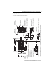
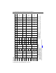
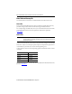
Dimensions
Motor Cat. No. AD
(1)
mm
(in.)
D
mm
(in.)
HD
(1)
mm
(in.)
L
(2)
mm
(in.)
L-LB
(3)
mm
(in.)
LA
mm
(in.)
LB
(2)
mm
(in.)
LD
(1), (2)
mm
(in.)
LE
(1), (2)
mm
(in.)
M
mm
(in.)
N1
mm
(in.)
N2
mm
(in.)
P
mm
(in.)
S
(4)
mm
(in.)
T1
mm
(in.)
T2
mm
(in.)
F
(5)
mm
(in.)
GE
(6)
mm
(in.)
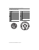
End of Shaft
Thread and
Depth of Hole
MPM-A/B1151
90.9
(3.58)
19.0
(0.748)
140.1
(5.52)
189.9
(7.48)
40.0
(1.575)
10.16
(0.40)
149.9
(5.90)
124.2
(4.89)
84.1
(3.31)
115.0
(4.528)
95.0
(3.74)
59.0
(2.32)
98.3
(3.87)
10.0
(0.401)
2.74
(0.108)
2.87
(0.113)
6.0
(0.236)
3.5
(0.138)
M6 x 1.0 - 6H
x16(0.63)
MPM-A/B1152
215.3
(8.48)
175.3
(6.90)
149.6
(5.89)
109.5
(4.31)
MPM-A/B1153
240.7
(9.48)
200.7
(7.90)
175.0
(6.89)
134.9
(5.31)
MPM-A/B1302
98.6
(3.88)
24.0
(0.945)
155.4
(6.12)
228.6
(9.0)
50.0
(1.969)
12.19
(0.48)
178.6
(7.03)
152.9
(6.02)
112.8
(4.44)
130.0
(5.118)
110.0
(4.33)
70.3
(2.77)
113.7
(4.48)
10.0
(0.401)
2.74
(0.108)
3.38
(0.133)
8.0
(0.315)
4.0
(0.158)
M8 x 1.25 - 6H
x19(0.75)
MPM
-A/B1304
279.4
(11.0)
229.4
(9.03)
203.7
(8.02)
163.6
(6.44)
MPM-A/B1651
113.4
(4.47)
28.0
(1.102)
185.2
(7.29)
286.6
(11.28)
60.0
(2.362)
14.0
(0.55)
226.6
(8.92)
200.2
(7.88)
160.0
(6.30)
165.0
(6.496)
130.0
(5.12)
81.0
(3.19)
143.5
(5.65)
12.0
(0.481)
3.12
(0.123)
3.38
(0.133)
8.0
(0.315)
4.0
(0.158)
M10x1.5-6H
x22(0.87)
MPM-A/B1652
337.4
(13.28)
277.4
(10.92)
251.0
(9.88)
210.8
(8.30)
MPM-A/B1653
388.2
(15.28)
328.2
(12.92)
301.8
(11.88)
261.6
(10.30)
MPM-A/B2152
154.0
(6.06)
38.0
(1.496)
246.5
(9.70)
354.6
(13.96)
80.0
(3.149)
17.8
(0.70)
274.6
(10.81)
234.4
(9.23)
163.3
(6.43)
215.0
(8.465)
180.0
(7.09)
108.0
(4.25)
184.9
(7.28)
14.50
(0.571)
3.73
(0.147)
3.86
(0.152)
10.0
(
0.394)
5.0
(0.197)
M12 x 1.75 - 6
H x 28 (1.10)
MPM-A/B2153
405.4
(15.96)
325.4
(12.81)
285.2
(11.23)
214.1
(8.43)
MPM-A/B2154
456.2
(17.96)
376.2
(14.81)
336.0
(13.23)
264.9
(10.43)
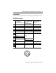
(1) See the diagram for dimension changes to MPM-x165x motors with an M40 power connector.
(2) For motors with a brake (MPM-xxxxxx-xxx4xx), adjust dimensions with these values:
MPM-x115 motors add 48.5 mm (1.91 in.) to L, LB, LD, and LE.
MPM-x130 motors add 48.5 mm (1.91 in.) to L, LB, LD, and LE.
MPM-x165 motors add 51.5 mm (2.03 in.) to L, LB, LD, and LE.
MPM-x215 motors add 88.9 mm (3.50 in.) to L, LB, LD. and LE.
(3) Tolerance is ±0.7 (±0.028).
(4) Tolerance is +0.36 (±0.007) for MPM-x115 and MPM-x130 motors, and +0.43 (±0.008) for MPM-x165 and MPM-x215.
(5) Tolerance is -0.03 (-0.001).
(6) Tolerance is -0.1 (-0.004) for MPM-x115x, -0.2 (-0.007) for MPM-x130x and MPM-x165x, and -0.2 (-0.008) for MPM-x215x.
Refer to Kinetix Rotary Motion Specifications Technical Data, publication GMC-TD001
, for pilot and shaft tolerances.