
Instruction Manual

MP-Series Low-inertia Servo Motor with 100 mm to 165 mm Frame Size 21
Rockwell Automation Publication MP-IN001H-EN-P - January 2014
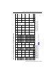
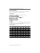
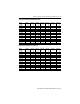
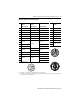
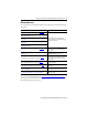
MPL-xxxxx-xx7xxx Connector Pin Descriptions
Pin High Resolution
Encoder
High Resolution
Encoder
Incremental Encoder Pin MPL-Axxx and
MPL-Bxxx
MPL-Axxx (230V) MPL-Bxxx (460V) MPL-A/Bxxxx-Hxxxx
1 SIN+ SIN+ AM+ A Phase U
(2)
(2) Power pins A, B, C, and D can also be labelled as U, V, W, and GND respectively. Brake pins F and G brake can also be labelled as + and - respectively.
Reserved pins E and H can also be numbered 1 or 2.
2 SIN- SIN- AM- B Phase V
(2)
3COS+ COS+ BM+ CPhase W
(2)
4 COS- COS- BM- D Ground
(2)
5 DATA+ DATA+ IM+ E Reserved
(2)
6 DATA- DATA- IM- F MBRK+
(2)
7
Reserved
Reserved
Reserved
GMBRK-
(2)
8H
Reserved
(2)
9EPWR_5V EPWR_5V L
(1)
(1) M23 (BEDC…) connector has nine pins, and the M40 (CEDE…) connector has eight pins.
10 ECOM ECOM
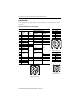
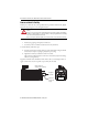
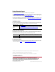
M23 Power/Brake Connector
M40 Power/Brake Connector
11
Reserved
EPWR_9V
Reserved
12 ECOM
13 TS+ TS+ TS+
14 TS- TS- TS-
15
Reserved Reserved
S1
16 S2
17 S3
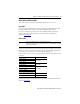
M23 Feedback Connector
B C
A
G
L
F
E
H
D
V
UW
12
+
-
1
2
3
4
5
6
7
8
9
10
11
12
13
14
17
15
16