Installation Instructions MP-Series Low-inertia Servo Motor with 100 mm to 165 mm Frame Size Catalog Numbers MPL-A310, MPL-A320, MPL-A330, MPL-A420, MPL-A430, MPL-A4530, MPL-A4540, MPL-A4560, MPL-A520, MPL-A540, MPL-A560, MPL-B310, MPL-B320, MPL-B330, MPL-B420, MPL-B430, MPL-B4530, MPL-B4540, MPL-B4560, MPL-B520, MPL-B540, MPL-B560, MPL-B580 Topic Page Important User Information 2 Catalog Number Explanation 3 About the MP-Series Low-inertia Motors 4 Before You Begin 4 Install the Motor 8 ATEX I
MP-Series Low-inertia Servo Motor with 100 mm to 165 mm Frame Size Important User Information Read this document and the documents listed in the additional resources section about installation, configuration, and operation of this equipment before you install, configure, operate, or maintain this product. Users are required to familiarize themselves with installation and wiring instructions in addition to requirements of all applicable codes, laws, and standards.
MP-Series Low-inertia Servo Motor with 100 mm to 165 mm Frame Size 3 Catalog Number Explanation MP L - x x 10 x - x x x x A x Factory Designated Options A = Standard H = ATEX protection rating of Group II, Zone 2 Mounting Flange A = IEC metric Brake 2 = No brake 4 = 24V DC brake Connectors 2 = Circular bayonet, facing shaft 7 = Circular DIN, right angle, 180° rotatable Shaft Key/Seal J = Shaft key/no shaft seal K = No shaft key/no shaft seal Feedback H = 2000 line encoder (1) M R = Multi-turn high-resolut
MP-Series Low-inertia Servo Motor with 100 mm to 165 mm Frame Size About the MP-Series Low-inertia Motors MP-Series™ low-inertia (Bulletin MPL) motors feature single-turn or multi-turn high resolution encoders, and are available with 24V DC brakes. These compact brushless servo motors meet the demanding requirements of high-performance motion systems. Before You Begin Remove all packing material from within and around the item.
MP-Series Low-inertia Servo Motor with 100 mm to 165 mm Frame Size 5 • Shaft seals are subject to wear and require periodic inspection and replacement. Replacement is recommended every 3 months, not to exceed 12 months, depending on use. Refer to Shaft Seal Kits on page 23 for more information on shaft seals. • Inspect the motor and seals for damage or wear on a regular basis. If damage or excessive wear is observed, replace the item.
MP-Series Low-inertia Servo Motor with 100 mm to 165 mm Frame Size Using Couplings and Pulleys Mechanical connections to the motor shaft, such as couplings and pulleys, require a torsionally rigid coupling or a reinforced timing belt. The high dynamic performance of servo motors can cause couplings, pulleys, or belts to loosen or slip over time. A loose or slipping connection can cause system instability and damage the motor shaft.
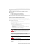
MP-Series Low-inertia Servo Motor with 100 mm to 165 mm Frame Size 7 Build and Install the Cables Correct cable routing and careful cable construction improves system electromagnetic compatibility (EMC). Follow these guidelines to build and install the cables: • Keep the wire lengths as short as possible. • Route noise sensitive wiring (encoder, serial, and I/O) away from input power and motor power wiring. • Separate cables by 0.3 m (1 ft) minimum for every 9 m (30 ft) of parallel run.
MP-Series Low-inertia Servo Motor with 100 mm to 165 mm Frame Size Grounding of Signal Wire Shields in a Power Cable Factory Supplied Shielded Signal Wires (two pairs) within Power Cable Overall Power Cable Shield Field Modified Signal Wire Shield (one of two) Contacts Overall Power Cable Shield All power and signal wire shields must connect to machine ground. 2090-XXNPMF-xxSxx (shown) contains two signal wire pairs. 2090-CPBM4DF-xxAFxx contains one signal wire pair.
MP-Series Low-inertia Servo Motor with 100 mm to 165 mm Frame Size 9 Change the Orientation of the Connectors MP-Series motors use two styles of connectors. The connector style is identified by a 2 or a 7 as the connector variable in the motor catalog number. For example, MPx-xxxxx-xx2xxx or MPx-xxxxx-xx7xxx: • A 2 indicates a circular bayonet connector, facing the shaft. • A 7 indicates a circular DIN, right angle, rotatable connector.
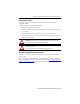
MP-Series Low-inertia Servo Motor with 100 mm to 165 mm Frame Size Rotatable Circular DIN Connector (catalog number MPL-xxxxx-xx7xxx) The circular DIN connector housing can be rotated up to 180° in either direction. ATTENTION: Connectors are designed to be rotated into a fixed position during motor installation, and remain in that position without further adjustment. Do not rotate the connector multiple times, and do not use tools or excessive force to rotate the connector.
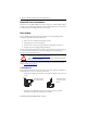
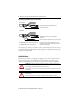
MP-Series Low-inertia Servo Motor with 100 mm to 165 mm Frame Size 11 Attach the Motor Cables Follow these steps to attach the feedback and power/brake cables after the motor is mounted. ATTENTION: Servo drive power must be turned off before connecting or disconnecting the cables to the motor, and if a cable is left disconnected at the motor end. Arcing or unexpected motion can occur if the feedback, power, or brake cables are connected or disconnected while power is applied to the servo drive.
MP-Series Low-inertia Servo Motor with 100 mm to 165 mm Frame Size 2. Form a drip loop in the cable (see page 4). 3. Carefully align the flat surface on the feedback or the power/brake cable plug (shown in the diagram) with the flat surface on the motor connector. IMPORTANT The motor orientation shown is used to clearly show the alignment marker on each cable socket. The recommended motor orientation when installed positions the connectors at the bottom of the motor.
MP-Series Low-inertia Servo Motor with 100 mm to 165 mm Frame Size 13 ATEX Installations If your motor has an ATEX rating for hazardous environments, complete the following step. The catalog number on ATEX motor nameplates ends with H, for example MPL-xxxxx-xxxxH. Verify the continuity and functionality of the thermal switch signals, TS+ and TS-, transmitted through the feedback cable that connects the motor to its controlling drive.
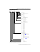
Rockwell Automation Publication MP-IN001H-EN-P - January 2014 MPL-xxxxx-xx2xxx Connector AD LE L D GE Shaft Key F MPL-x3xx = 5 x 5 x 25 MPL-x4xx = 6 x 6 x 25 MPL-x45xx = 8 x 7 x 32 MPL-x520, x540, x560 = 8 x 7 x 40 MPL-x580 = 10 x 8 x 59 T LA L-LB P S (diameter of bolt circle) M (diameter of holes) (1) Electronic zero (index pulse or Stegmann ABS = 0) occurs when the shaft key or dimple (not shown) is aligned with the connectors (as shown). HD Add for High Resolution End Cap 3.3 (0.
106.2 (4.18) 91.5 (3.6) 83.9 (3.3) 80.9 (3.19) 28.0 (1.1) 24.0 (0.945) 19.0 (0.748) 16.0 (0.629) D* mm (in.) 178.1 (7.01) 148.3 (5.84) 132.8 (5.23) 125.7 (4.95) HD mm (in.) 164.7 (6.49) 190.1 (7.49) 215.5 (8.49) 186.5 (7.35) 211.9 (8.345) 225.2 (8.87) 250.6 (9.87) 304.7 (11.99) 233.7 (9.20) 284.5 (11.20) 335.3 (13.20) 406.1 (15.99) L (1), (2) mm (in.) 60.0 (2.38) 50.0 (1.97) 40.0 (1.575) 40.0 (1.58) L-LB (3) mm (in.) 13.97 (0.55) 12.2 (0.48) 10.2 (0.40) 9.9 (0.39) LA mm (in.) 124.
Rockwell Automation Publication MP-IN001H-EN-P - January 2014 LE AD + 22.99 (0.90) HD + 22.95 (9.01) LD + 2.0 (0.07) LE - 31 (1.22) M23 Feedback Connector shown for comparison LD Dimensions for M40 Power/Brake Connector on the MPL-A5xxx-xx7xxx and the MPL-B580x-xx7xxx motors.
D* mm (in.) HD mm (in.) L (1) mm (in.) L-LB (2) mm (in.) LA mm (in.) LB (1) mm (in.) LD (1) mm (in.) LE (1) mm (in.) MPL-A/B310 168.0 128.0 62.0 102.0 (6.62) (5.04) (2.45) (4.03) 87.2 16.0 132.0 40.0 9.90 193.0 153.0 88.0 128.0 MPL-A/B320 (3.44) (0.629) (5.20) (1.575) (0.39) (7.62) (6.04) (3.45) (5.03) 219.0 179.0 113.0 153.0 MPL-A/B330 (8.62) (7.04) (4.45) (6.03) 190.0 150.0 84.0 124.0 MPL-A/B420 (7.48) (5.90) (3.31) (4.89) 90.9 19.0 140.1 40.0 10.16 (3.58) (0.749) (5.52) (1.575) (0.40) 215.0 175.
MP-Series Low-inertia Servo Motor with 100 mm to 165 mm Frame Size Motor Load Force Ratings Motors are capable of operating with a sustained shaft load. The radial and axial load force location is shown in the figure, and maximum values are in the tables. Load Forces on Shaft Radial load force applied at center of shaft extension. Axial load force. The following tables represent 20,000 hour L10 bearing fatigue life at various loads and speeds.
MP-Series Low-inertia Servo Motor with 100 mm to 165 mm Frame Size 19 Axial Load Force Ratings (maximum radial load) Motor Cat. No.
MP-Series Low-inertia Servo Motor with 100 mm to 165 mm Frame Size Connector Data These tables provide the signal descriptions for the feedback, power, and brake pinouts on the connectors.
MP-Series Low-inertia Servo Motor with 100 mm to 165 mm Frame Size 21 MPL-xxxxx-xx7xxx Connector Pin Descriptions Pin High Resolution Encoder High Resolution Encoder Incremental Encoder Pin MPL-Axxx and MPL-Bxxx MPL-Axxx (230V) MPL-Bxxx (460V) MPL-A/Bxxxx-Hxxxx 1 SIN+ SIN+ AM+ A Phase U (2) 2 SIN- SIN- AM- B Phase V (2) 3 COS+ COS+ BM+ C Phase W (2) 4 COS- COS- BM- D Ground (2) 5 DATA+ DATA+ IM+ E Reserved (2) 6 DATA- DATA- IM- F MBRK+ (2) G MBRK- (2) 7 Reserv
MP-Series Low-inertia Servo Motor with 100 mm to 165 mm Frame Size Remove and Install a Shaft Key Shaft keys are constructed of steel. The specified tolerance provides an interference fit (slightly larger than the opening) for a secure and rigid connection. ATTENTION: Do not strike the motor’s shaft, couplings, or pulleys with tools during installation or removal of the shaft key.
MP-Series Low-inertia Servo Motor with 100 mm to 165 mm Frame Size 23 Motor Cables and Accessory Kits This section describes accessories that are available for MP-Series low-inertia motors. Motor Cables Factory manufactured feedback and power cables are available in standard cable lengths. They provide the sealing needed to achieve environmental ratings and shield termination.
MP-Series Low-inertia Servo Motor with 100 mm to 165 mm Frame Size Specifications Attribute Value Temperature, operating 0…40 °C (32…104 °F) (4) Temperature, storage -30…70 °C (-22…158 °F) Relative humidity, storage 5…95% noncondensing Atmosphere, storage IP Rating (1) of motor with optional shaft seal Noncorrosive (2) installed Motor without a shaft seal, and mounted in this direction: Shaft down Shaft horizontal Shaft up ATEX rating (3) IP 66 (dust tight, heavy jet spray) IP53 IP51 IP50
MP-Series Low-inertia Servo Motor with 100 mm to 165 mm Frame Size 25 Additional Resources These documents contain additional information concerning related products from Rockwell Automation.
Rockwell Automation Support Rockwell Automation provides technical information on the Web to assist you in using its products. At http://www.rockwellautomation.com/support you can find technical and application notes, sample code, and links to software service packs. You can also visit our Support Center at https://rockwellautomation.custhelp.com/ for software updates, support chats and forums, technical information, FAQs, and to sign up for product notification updates.