
Manual

MP-Series Low-inertia Brushless Servo Motors with 75 mm or Smaller Frame Sizes 17
Rockwell Automation Publication MP-IN006C-EN-P - January 2014
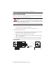
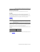
Connector Data
This table provides the signal descriptions for the feedback, power, and brake pinouts on the
connectors.
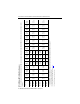
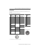
M23 Feedback and Power/Brake Pin Descriptions
Pin High Resolution
Encoder
High Resolution
Encoder
Incremental Encoder Pin MPL-Axxx and
MPL-Bxxx
MPL-Axxx (230V) MPL-Bxxx (460V) MPL-A/Bxxxx-Hxxxx
1Sin+ Sin+ A+ A Phase U
(1)
(1) The U, V and W power phases can also be labelled as R, S, and T respectively.
2 Sin- Sin- A- B Phase V
(1)
3Cos+ Cos+ B+ CPhase W
(1)
4 Cos- Cos- B- D Ground
5 Data+ Data+ I+ E Reserved
6Data- Data- I- FBR+
7
Reserved
Reserved
Reserved
GBR-
8H
Reserved
9 +5V DC +5 V DC L
10 Common Common
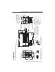
M23 Power/Feedback Connector
11
Reserved
+9V DC
Reserved
12 Common
13 TS+ TS+ TS+
14 TS- TS- TS-
15
Reserved Reserved
S1
16 S2
17 S3
M23 Feedback Connector
B C
A
G
L
F
E
H
D
1
2
3
4
5
6
7
8
9
10
11
12
13
14
17
15
16