Installation Instructions MP-Series Low-inertia Brushless Servo Motors with 75 mm or Smaller Frame Sizes Catalog Numbers MPL-A1510, MPL-A1520, MPL-A1530, MPL-A210, MPL-A220, MPL-A230, MPL-B1510, MPL-B1520, MPL-B1530, MPL-B210, MPL-B220, MPL-B230 Topic Page Important User Information 2 Catalog Number Explanation 3 About the MP-Series Low-inertia Motors 4 Before You Begin 4 Install the Motor 9 Product Dimensions 13 Motor Load Force Ratings 15 Connector Data 17 Remove and Install a Shaft Key
MP-Series Low-inertia Brushless Servo Motors with 75 mm or Smaller Frame Sizes Important User Information Read this document and the documents listed in the additional resources section about installation, configuration, and operation of this equipment before you install, configure, operate, or maintain this product. Users are required to familiarize themselves with installation and wiring instructions in addition to requirements of all applicable codes, laws, and standards.
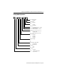
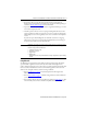
MP-Series Low-inertia Brushless Servo Motors with 75 mm or Smaller Frame Sizes 3 Catalog Number Explanation MP L - x x xx x - x J 7 x A A Factory Designated Options A = Standard Mounting Flange A = IEC metric Brake 2 = No brake 4 = 24V DC brake Connectors 7 = Circular DIN, right angle, 180° rotatable Enclosure/Shaft Key/Shaft Seal J = IP66 housing/shaft key/no shaft seal Feedback E = Single-turn high-resolution encoder H = 2000 line encoder V = Multi-turn high-resolution encoder Rated Speed P = 5000 rpm T
MP-Series Low-inertia Brushless Servo Motors with 75 mm or Smaller Frame Sizes About the MP-Series Low-inertia Motors MP-Series™ low-inertia (Bulletin MPL) motors feature single-turn or multi-turn high resolution encoders, and are available with 24V DC brakes. These compact brushless servo motors meet the demanding requirements of high-performance motion systems. Before You Begin Remove all packing material from within and around the item.
MP-Series Low-inertia Brushless Servo Motors with 75 mm or Smaller Frame Sizes 5 • Shaft seals are subject to wear and require periodic inspection and replacement. Replacement is recommended every 3 months, not to exceed 12 months, depending on use. Refer to Shaft Seal Kits on page 19 for more information. • Inspect the motor and seals for damage or wear on a regular basis. If damage or excessive wear is observed, replace the item.
MP-Series Low-inertia Brushless Servo Motors with 75 mm or Smaller Frame Sizes Using Couplings and Pulleys Mechanical connections to the motor shaft, such as couplings and pulleys, require a torsionally rigid coupling or a reinforced timing belt. The high dynamic performance of servo motors can cause couplings, pulleys, or belts to loosen or slip over time. A loose or slipping connection can cause system instability and damage the motor shaft.
MP-Series Low-inertia Brushless Servo Motors with 75 mm or Smaller Frame Sizes 7 Build and Install the Cables Correct cable routing and careful cable construction improves system electromagnetic compatibility (EMC). Follow these guidelines to build and install the cables: • Keep the wire lengths as short as possible. • Route noise sensitive wiring (encoder, serial, and I/O) away from input power and motor power wiring. • Separate cables by 0.3 m (1 ft) minimum for every 9 m (30 ft) of parallel run.
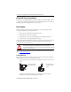
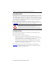
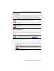
MP-Series Low-inertia Brushless Servo Motors with 75 mm or Smaller Frame Sizes Power Cable Shielding Factory Supplied } Shielded Signal Wires (two) within Power Cable Overall Power Cable Shield Field Modified Loop signal shield (one of two) to overall power cable shield. Verift that the power cable ground clamp on the drive contacts all (three) cable shields. Brake Control and Power Regulation The DC power source for a permanent magnet brake, such as that on the MP-Series servo motor with 75 mm (2.
MP-Series Low-inertia Brushless Servo Motors with 75 mm or Smaller Frame Sizes 9 Install the Motor MP-Series motors include a mounting pilot for aligning the motor on the machine. Preferred fasteners are stainless steel. The installation must comply with all local regulations and use equipment and installation practices that promote safety and electromagnetic compatibility.
MP-Series Low-inertia Brushless Servo Motors with 75 mm or Smaller Frame Sizes Mount the Motor Follow these steps to mount the motor. ATTENTION: Damage can occur to the motor bearings and the feedback device if sharp impact to the shaft is applied during installation of couplings and pulleys. Do not strike the shaft, couplings, or pulleys with tools during installation or removal. 1.
MP-Series Low-inertia Brushless Servo Motors with 75 mm or Smaller Frame Sizes 11 Attach the Motor Cables Follow these steps to attach the feedback and power/brake cables after the motor is mounted. ATTENTION: Servo drive power must be turned off before connecting or disconnecting the cables to the motor, and if a cable is left disconnected at the motor end. Arcing or unexpected motion can occur if the feedback, power, or brake cables are connected or disconnected while power is applied to the servo drive.
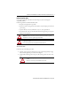
MP-Series Low-inertia Brushless Servo Motors with 75 mm or Smaller Frame Sizes 2. Form a drip loop in the cable (see page 4). 3. Carefully align the flat surface on the feedback or the power/brake cable plug (shown in the diagram) with the flat surface on the motor connector. IMPORTANT The motor orientation shown is used to clearly show the alignment marker on each cable socket. The recommended motor orientation when installed positions the connectors at the bottom of the motor.
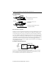
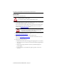
53.9 (2.12) G F HD MPL-A/B1510, -A/B1520, -A/B1530 = 3 x 3 x 14 Key MPL-A/B210, -A/B220, -A/B230 = 4 x 4 x 16 Key Shaft Detail with Key AD Connector housings can be rotated within a range of 180° 2.8 ±0.30 (0.110 ±0.012) LD L MPL-A/B 1xxx and MPL-AB2xx Motors: Ø 11.89…11.95 (0.468…0.470) Detail A LB Dimensions are in mm (in.) This section provides dimensions for the motors.
Rockwell Automation Publication MP-IN006C-EN-P - January 2014 111.2 (4.38) 2.50 (0.098) 9.0 (0.35) 89.4 (3.52) 188.3 (7.41) 162.8 (6.41) 137.3 (5.40) 165.6 (6.52) 140.1 (5.52) 114.6 (4.51) 151.5 (5.96) 126.5 (4.98) 22.7 (0.894) 19.7 (0.776) mm (in.) L-LB (2) 11.0 (0.43) 9.0 (0.35) mm (in.) D (3) 75.0 (2.953) 63.0 (2.480) mm (in.) M Tolerance for this dimension is ±0.7 mm (±0.028 in.). For keyway, shaft diameter, and pilot diameter tolerances, see page 15.
MP-Series Low-inertia Brushless Servo Motors with 75 mm or Smaller Frame Sizes 15 Tolerances and Supplemental Dimensions Shaft, Pilot, and Keyway Tolerances MPL-A/B15xx MPL-A/B2xx Shaft Runout (T.I.R.) 0.030 (0.0012) 0.035 (0.0014) Pilot Eccentricity (T.I.R.) 0.08 (0.0031) 0.08 (0.0031) Max Face Runout (T.I.R.) 0.08 (0.0031) 0.08 (0.0031) Keyway Depth (G) 7.10…7.20 (0.280…0.283) 8.40…8.50 (0.331…0.335) Keyway Width (F) 2.971…2.996 (0.117…0.118) 3.97…4.00 (0.156…0.
MP-Series Low-inertia Brushless Servo Motors with 75 mm or Smaller Frame Sizes Axial Load Force Ratings (maximum radial load) Motor Cat. No.
MP-Series Low-inertia Brushless Servo Motors with 75 mm or Smaller Frame Sizes 17 Connector Data This table provides the signal descriptions for the feedback, power, and brake pinouts on the connectors.
MP-Series Low-inertia Brushless Servo Motors with 75 mm or Smaller Frame Sizes Remove and Install a Shaft Key Shaft keys are constructed of steel. The specified tolerance provides an interference fit (slightly larger than the opening) for a secure and rigid connection. ATTENTION: Do not strike the motor’s shaft, couplings, or pulleys with tools during installation or removal of the shaft key.
MP-Series Low-inertia Brushless Servo Motors with 75 mm or Smaller Frame Sizes 19 Motor Cables and Accessory Kits This section describes accessories that are available for MP-Series low-inertia motors. Motor Cables Factory manufactured feedback and power cables are available in standard cable lengths. They provide the sealing needed to achieve environmental ratings and shield termination.
MP-Series Low-inertia Brushless Servo Motors with 75 mm or Smaller Frame Sizes Specifications Always store a motor in a clean and dry location within these environmental conditions. Appropriate mounting, cabling, and a shaft seal can be required to attain a specific IP rating. Exterior surfaces of the MP-Series small frame servo motors are made from these materials.
MP-Series Low-inertia Brushless Servo Motors with 75 mm or Smaller Frame Sizes 21 Additional Resources These documents contain additional information concerning related products from Rockwell Automation.
Rockwell Automation Support Rockwell Automation provides technical information on the Web to assist you in using its products. At http://www.rockwellautomation.com/support you can find technical and application notes, sample code, and links to software service packs. You can also visit our Support Center at https://rockwellautomation.custhelp.com/ for software updates, support chats and forums, technical information, FAQs, and to sign up for product notification updates.