Installation Instructions MP-Series Low-inertia Servo Motor with 215 mm or Larger Frame Size Catalog Numbers MPL-B640, MPL-B660, MPL-B680, MPL-B860, MPL-B880, MPL-B960, MPL-B980 Topic Page Important User Information 2 Catalog Number Explanation 3 About the MP-Series Low-inertia Motors 4 Before You Begin 4 Install the Motor 8 ATEX Installations 13 Product Dimensions 14 Motor Load Force Ratings 16 Connector Data 18 Remove and Install a Shaft Key 19 Motor Cables and Accessory Kits 20 S
MP-Series Low-inertia Servo Motor with 215 mm or Larger Frame Size Important User Information Read this document and the documents listed in the additional resources section about installation, configuration, and operation of this equipment before you install, configure, operate, or maintain this product. Users are required to familiarize themselves with installation and wiring instructions in addition to requirements of all applicable codes, laws, and standards.
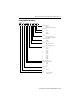
MP-Series Low-inertia Servo Motor with 215 mm or Larger Frame Size 3 Catalog Number Explanation MP L - B x 80 x - x x x x A x Factory Designated Options A = Standard H = ATEX protection rating of Group II, Zone 2 Mounting Flange A = IEC metric Brake 2 = No brake 4 = 24V DC brake Connectors 2 = Bayonet, right angle, 180° rotatable 7 = Circular DIN, right angle, 180° rotatable Enclosure/Shaft Key/Shaft Seal J = Shaft key K = No shaft key Feedback M = Multi-turn high-resolution encoder S
MP-Series Low-inertia Servo Motor with 215 mm or Larger Frame Size About the MP-Series Low-inertia Motors MP-Series™ low-inertia (Bulletin MPL) motors feature single-turn or multi-turn high resolution encoders, and are available with 24V DC brakes. These compact brushless servo motors meet the demanding requirements of high-performance motion systems. Before You Begin Remove all packing material, wedges, and braces from within and around the item.
MP-Series Low-inertia Servo Motor with 215 mm or Larger Frame Size 5 • Shaft seals are subject to wear and require periodic inspection and replacement. Replacement is recommended every 3 months, not to exceed 12 months, depending on use. Refer to Shaft Seal Kits on page 20 for more information on shaft seals. • Inspect the motor and seals for damage or wear on a regular basis. If damage or excessive wear is observed, replace the item.
MP-Series Low-inertia Servo Motor with 215 mm or Larger Frame Size Using Couplings and Pulleys Mechanical connections to the motor shaft, such as couplings and pulleys, require a torsionally rigid coupling or a reinforced timing belt. The high dynamic performance of servo motors can cause couplings, pulleys, or belts to loosen or slip over time. A loose or slipping connection can cause system instability and damage the motor shaft.
MP-Series Low-inertia Servo Motor with 215 mm or Larger Frame Size 7 Build and Install the Cables Correct cable routing and careful cable construction improves system electromagnetic compatibility (EMC). Follow these guidelines to build and install the cables: • Keep the wire lengths as short as possible. • Route noise sensitive wiring (encoder, serial, and I/O) away from input power and motor power wiring. • Separate cables by 0.3 m (1 ft) minimum for every 9 m (30 ft) of parallel run.
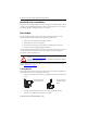
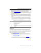
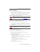
MP-Series Low-inertia Servo Motor with 215 mm or Larger Frame Size Grounding of Signal Wire Shields in a Power Cable Factory Supplied Shielded Signal Wires (two pairs) within Power Cable Overall Power Cable Shield Field Modified Signal Wire Shield (one of two) Contacts Overall Power Cable Shield All power and signal wire shields must connect to machine ground. 2090-XXNPMF-xxSxx (shown) contains two signal wire pairs. 2090-CPBM4DF-xxAFxx contains one signal wire pair.
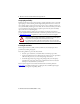
MP-Series Low-inertia Servo Motor with 215 mm or Larger Frame Size 9 Change Connector Orientation You can rotate the connector housings up to 180°. • The M23 feedback connector and the M40 power/brake connector are rotatable. • The M58 power/brake connector, on MPL-B8xx and MPL-B9xx motors with higher current requirements, must be removed and repositioned in 90° increments.
MP-Series Low-inertia Servo Motor with 215 mm or Larger Frame Size Mount the Motor Follow these steps to mount the motor. ATTENTION: Damage can occur to the motor bearings and the feedback device if sharp impact to the shaft is applied during installation of couplings and pulleys. Do not strike the shaft, couplings, or pulleys with tools during installation or removal. 1.
MP-Series Low-inertia Servo Motor with 215 mm or Larger Frame Size 11 Attach the Motor Cables Follow these steps to attach the feedback and power/brake cables after the motor is mounted. ATTENTION: Servo drive power must be turned off before connecting or disconnecting the cables to the motor, and if a cable is left disconnected at the motor end. Arcing or unexpected motion can occur if the feedback, power, or brake cables are connected or disconnected while power is applied to the servo drive.
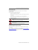
MP-Series Low-inertia Servo Motor with 215 mm or Larger Frame Size 2. Form a drip loop in the cable (see page 4). 3. Carefully align the flat surface on the feedback or the power/brake cable plug (shown in the diagram) with the flat surface on the motor connector. IMPORTANT The motor orientation shown is used to clearly show the alignment marker on each cable socket. The recommended motor orientation when installed positions the connectors at the bottom of the motor.
MP-Series Low-inertia Servo Motor with 215 mm or Larger Frame Size 13 ATEX Installations If your motor has an ATEX rating for hazardous environments, complete the following step. The catalog number on ATEX motor nameplates ends with H, for example MPL-xxxxx-xxxxH. Verify the continuity and functionality of the thermal switch signals, TS+ and TS-, transmitted through the feedback cable that connects the motor to its controlling drive.
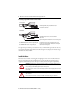
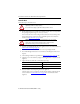
Rockwell Automation Publication MP-IN002D-EN-P - January HD HD AD AD L LE M58 Power/Brake Connector on MPL-B8xx-xx7xAA and MPL-B9xx-xx7xAA with Higher Current Requirements LD M40 Power/Brake Connector on MPL-B6xx-xx7xAA, MPL-B8xx-xx7xAA, and MPL-B9xx-xx7xAA LE 3.86 (0.152) Tooling Cut Only for MPL-B6xx LB This section provides dimensions for the motors. Product Dimensions 3.86 mm (0.152 in.) Only MPL-B6xx MPL-B9xx Ø 51.89 ±.07 mm (2.043 ± 0.003 in.) MPL-B8xx Ø 44.91 ±.05 mm (1.768 ± 0.
MP-Series Low-inertia Servo Motor with 215 mm or Larger Frame Size 15 The dimensions in the table are for non-brake motors with a single-turn or multi-turn encoder. Footnotes provide tolerances for the common dimensions, and the additional dimensions for the brake motors. Dimensions Motor Cat. No. AB AD D (3) F (4) GE (5) HD L (7), (8) L-LB (8) LA mm (in.) mm (in.) mm (in.) mm (in.) mm (in.) mm (in.) mm (in.) mm (in.) mm (in.) 80.0 (3.150) 17.8 (0.70) 303.8 (11.
MP-Series Low-inertia Servo Motor with 215 mm or Larger Frame Size Dimensions (continued) Motor Cat. No. LB (1) LD (1) LE (1) M N (2) P S (3) T mm (in.) mm (in.) mm (in.) mm (in.) mm (in.) mm (in.) mm (in.) mm (in.) MPL-B640 223.8 (8.81) 183.6 (7.23) 112.5 (3.15) MPL-B660 274.6 (10.81) 234.4 (9.23) 163.3 (6.43) MPL-B680 325.4 (12.81) 285.2 (11.23) 214.1 (8.43) MPL-B860 284.4 (17.45) 242.6 (9.55) 171.4 (6.75) MPL-B880 335.2 (13.20) 293.4 (11.55) 222.2 (8.
MP-Series Low-inertia Servo Motor with 215 mm or Larger Frame Size 17 Radial Load Force Ratings Motor Cat. No.
MP-Series Low-inertia Servo Motor with 215 mm or Larger Frame Size Connector Data This table provides the signal descriptions for the feedback, power, and brake pinouts on the connectors.
MP-Series Low-inertia Servo Motor with 215 mm or Larger Frame Size 19 Remove and Install a Shaft Key Shaft keys are constructed of steel. The specified tolerance provides an interference fit (slightly larger than the opening) for a secure and rigid connection. ATTENTION: Do not strike the motor’s shaft, couplings, or pulleys with tools during installation or removal of the shaft key.
MP-Series Low-inertia Servo Motor with 215 mm or Larger Frame Size Motor Cables and Accessory Kits This section describes accessories that are available for MP-Series low-inertia motors. Motor Cables Factory manufactured feedback and power cables are available in standard cable lengths. They provide the sealing needed to achieve environmental ratings and shield termination.
MP-Series Low-inertia Servo Motor with 215 mm or Larger Frame Size 21 Specifications Attribute Value Temperature, operating 0…40 °C (32…104 °F) (3) Temperature, storage -30…70 °C (-22…158 °F) Relative humidity, storage 5…95% noncondensing Atmosphere, storage Noncorrosive (1) IP Rating Motor with a shaft seal (2) Motor without a shaft seal, and mounted in this direction: Shaft down Shaft horizontal Shaft up (1) IP66 - dust tight, powerful water jets (4) IP53 - dust tight, powerful water jets IP5
MP-Series Low-inertia Servo Motor with 215 mm or Larger Frame Size Additional Resources These documents contain additional information concerning related products from Rockwell Automation.
MP-Series Low-inertia Servo Motor with 215 mm or Larger Frame Size 23 Notes: Rockwell Automation Publication MP-IN002D-EN-P - January
Rockwell Automation Support Rockwell Automation provides technical information on the Web to assist you in using its products. At http://www.rockwellautomation.com/support you can find technical and application notes, sample code, and links to software service packs. You can also visit our Support Center at https://rockwellautomation.custhelp.com/ for software updates, support chats and forums, technical information, FAQs, and to sign up for product notification updates.