
Owner's manual
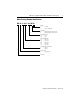
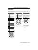
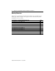
Table Of Contents
- MP-IN003C-EN-P — April 2003
- Front Cover
- Catalog Numbers
- Table of Contents
- Receiving and Storage
- Environmental Ratings
- Motor Catalog Number Identification
- Before You Install the Motor
- Installing Your Motor
- Connector Data
- Mounting Dimensions
- Housing and Output Flange Connections
- Motor Load Force Ratings
- Holding Brake
- Cables and Connector Kits
- Gear Lubricant
- Related Documentation
- Back Cover
- Web Links
MP-Series Integrated Gear Motor Installation Instructions 9
Publication MP-IN003C-EN-P — April 2003
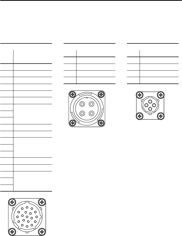
Connector Data
The tables below list the signal descriptions for the feedback, power, and
brake connector pins.
Feedback Connector Power Connector Brake Connector
High Resolution Pin Signal Pin Signal
Pin Encoder
A Phase U A BR+
A Sin+ B Phase V B Reserved
B Sin- C Phase W C BR-
C Cos+ D Ground D Reserved
DCos-
E Data+
F Data-
G Reserved
H
J
K +5V dc
LCommon
M Reserved Note: Ensure that proper
polarity is maintained
when wiring a brake
connector.
N
P
RTS+
STS-
T Reserved
U
V
A
B
C
D
ITT Cannon
TNM 16-4
A
B
C
D
ITT Cannon
TNM 10-4
A
B
C
D
E
F
G
H
J
K
L
M
N
P
R
S
T
U
V
ITT Cannon
TNM 16-19