
Owner's manual
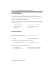
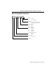
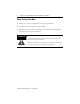
Table Of Contents
- MP-IN003C-EN-P — April 2003
- Front Cover
- Catalog Numbers
- Table of Contents
- Receiving and Storage
- Environmental Ratings
- Motor Catalog Number Identification
- Before You Install the Motor
- Installing Your Motor
- Connector Data
- Mounting Dimensions
- Housing and Output Flange Connections
- Motor Load Force Ratings
- Holding Brake
- Cables and Connector Kits
- Gear Lubricant
- Related Documentation
- Back Cover
- Web Links
MP-Series Integrated Gear Motor Installation Instructions 5
Publication MP-IN003C-EN-P — April 2003
Installing Your Motor
The installation must comply with all local regulations and use of
equipment and installation practices that promote electromagnetic
compatibility and safety.
All motors have a dowel pin hole for precisely aligning the motor output
on a machine. Bolt hole sizes are listed in Mounting Dimensions
beginning on page 10, and bolt torque requirements are listed in Housing
and Output Flange Connections beginning on page 22.
ATTENTION
!
Unmounted motors, disconnected mechanical
connections, and disconnected cables are dangerous if
power is applied.
Disassembled equipment should be appropriately
identified (tagged-out) and access to electrical power
restricted (locked-out).
Before applying power to the motor, remove any
mounting bolts and screws, or other mechanical objects
which could be thrown from the motor.
Failure to observe these safety procedures could result in
personal injury.
ATTENTION
!
Ensure that cables are installed and restrained to prevent
uneven tension or flexing at the cable connectors.
Excessive and uneven lateral force at the cable
connectors may result in the connector’s environmental
seal opening and closing as the cable flexes.
Failure to observe these safety procedures could result in
damage to the motor and its components.