
Owner's manual
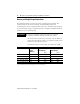
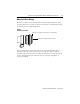
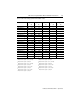
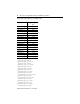
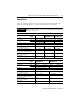
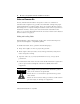
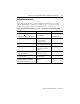
Table Of Contents
- MP-IN003C-EN-P — April 2003
- Front Cover
- Catalog Numbers
- Table of Contents
- Receiving and Storage
- Environmental Ratings
- Motor Catalog Number Identification
- Before You Install the Motor
- Installing Your Motor
- Connector Data
- Mounting Dimensions
- Housing and Output Flange Connections
- Motor Load Force Ratings
- Holding Brake
- Cables and Connector Kits
- Gear Lubricant
- Related Documentation
- Back Cover
- Web Links
MP-Series Integrated Gear Motor Installation Instructions 29
Publication MP-IN003C-EN-P — April 2003
If you choose to build your own cables, the following connector kits are
available for MP-Series Integrated Gear Motors. These solder-type
connectors mate with the motor-mounted connectors and provide
environmental sealing with shield termination.
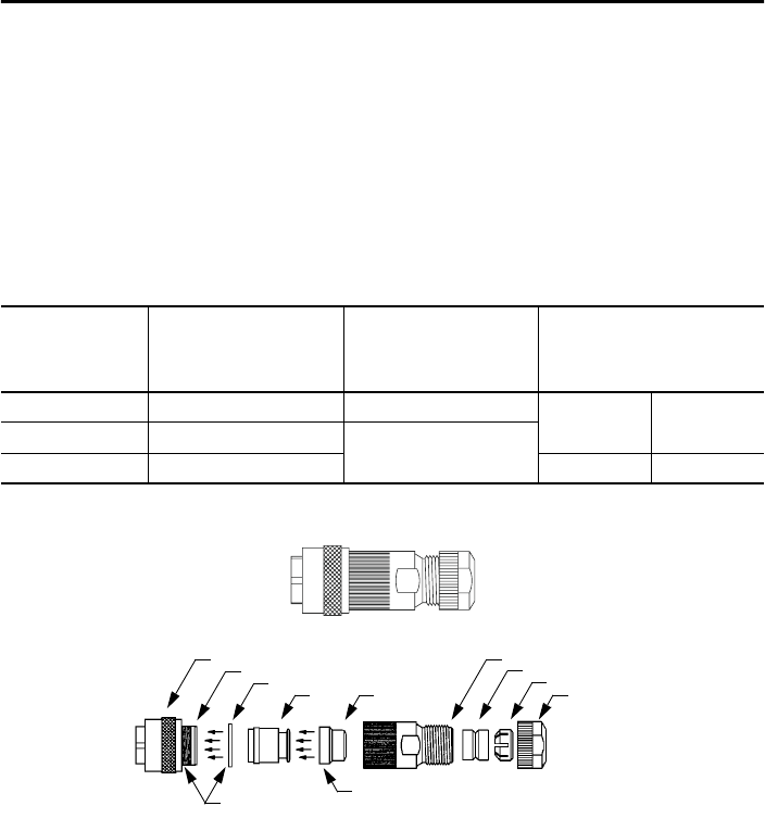
Each connector kit includes the requisite number and size of solder-type
contact pins, a connector housing, and a connector backshell. As an
example, finished and exploded views of the connector kit are shown
below.
Gear Lubricant
Gear units are permanently lubricated at the factory.
Catalog Number Connector
Type
Accepts
Wire Gauge
1
Accepts
Cable Diameter Gauge
mm
2
(AWG)
mm
2
(in.)
2090-MPPC-S Power - Straight 2.5-4.0 (14-12) 7.9-12.4 (0.31-0.49)
2090-MPFC-S Feedback - Straight 0.08-2.5 (28-14)
2090-MPBC-S Brake - Straight 4.3-7.4 (0.17-0.29)
1
Refer to your drive’s installation manual for recommended wire gauges.
Clamp Nut
Cable Clamp Ring
Sealing Grommet
EndbellConnector Coupling Ring
Bushing
Snap Ring Cone
onto Bushing
Install O-Ring
on groove in
Connector Housing
Ring Cone
O-Ring
Connector Housing