
Owner's manual
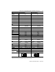
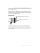
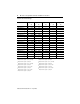
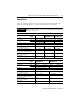
Table Of Contents
- MP-IN003C-EN-P — April 2003
- Front Cover
- Catalog Numbers
- Table of Contents
- Receiving and Storage
- Environmental Ratings
- Motor Catalog Number Identification
- Before You Install the Motor
- Installing Your Motor
- Connector Data
- Mounting Dimensions
- Housing and Output Flange Connections
- Motor Load Force Ratings
- Holding Brake
- Cables and Connector Kits
- Gear Lubricant
- Related Documentation
- Back Cover
- Web Links
MP-Series Integrated Gear Motor Installation Instructions 23
Publication MP-IN003C-EN-P — April 2003
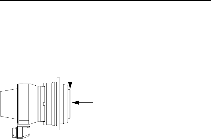
Motor Load Force Ratings
Motors are capable of operating with a sustained shaft load. The radial
and axial load force location is shown in the figure, and maximum values
for motors are in the following tables.
Figure 2
Load Forces on Shaft
The following tables represent 20,000 hour L
10
bearing fatigue life at
various loads and speeds. This 20,000 hour life does not account for
possible application-specific life reduction that may occur due to bearing
grease contamination from external sources, improper alignment, or
excessive loading.
Axial load force applied at shaft centerline
Radial load force applied at mounting end of output flange