
Owner's manual
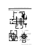


Table Of Contents
- MP-IN003C-EN-P — April 2003
- Front Cover
- Catalog Numbers
- Table of Contents
- Receiving and Storage
- Environmental Ratings
- Motor Catalog Number Identification
- Before You Install the Motor
- Installing Your Motor
- Connector Data
- Mounting Dimensions
- Housing and Output Flange Connections
- Motor Load Force Ratings
- Holding Brake
- Cables and Connector Kits
- Gear Lubricant
- Related Documentation
- Back Cover
- Web Links
MP-Series Integrated Gear Motor Installation Instructions 11
Publication MP-IN003C-EN-P — April 2003
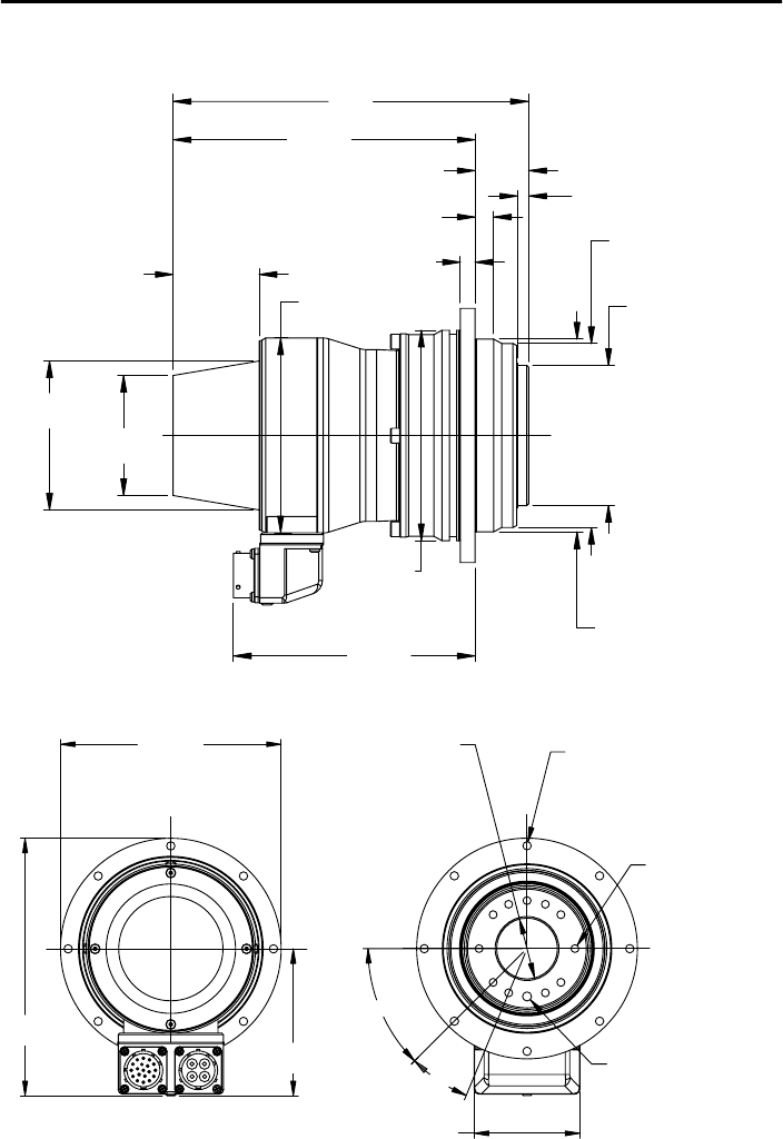
Figure 1
References for Motor Mounting Dimensions
AF
LD
AG
N
AC
LE
AE
LA
D
NB
E
L-LB
T
DB
P
HD
AD
BE
M (dia. of bolt circle
S (diameter of hole)
MA (thread and depth)
MB (diameter of dowel)
BHP (Bolt Hole Pattern)
BHPA (Auxiliary
Bolt Hole Pattern)
LB
MC (dia. of bolt circle
Dowel pin hole aligned
at electronic zero
MPG-x025-091x22 shown
on output flange)
on motor housing)
L