Installation Instructions MP-Series Integrated Gear Motors (Catalog Numbers: MPG-A004-031, MPG-A004-091, MPG-A010-031, MPG-A010-091, MPG-B010-031, MPG-B010-091, MPG-A025-031, MPG-A025-091, MPG-B025-031, MPG-B025-091, MPG-A050-031, MPG-A050-091, MPG-B050-031, MPG-B050-091, MPG-A110-031, MPG-A110-091, MPG-B110-031, and MPG-B110-091) These Installation Instructions describe how to install MP-Series Integrated Gear Motors.
MP-Series Integrated Gear Motor Installation Instructions Receiving and Storage The customer is responsible for inspecting the equipment before accepting the shipment from the freight company. Check the item(s) you receive against your purchase order. Notify the carrier of any shipping damage or missing items immediately.
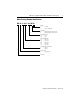
MP-Series Integrated Gear Motor Installation Instructions 3 Motor Catalog Number Identification MP G - A 010 - 031 M 22 BRAKE 22 = No Brake 24 = 24V dc Holding Brake FEEDBACK M = Multi-turn High Resolution Encoder S = Single-turn High Resolution Encoder GEAR REDUCTION 031 = 31 to 1 091 = 91 to 1 MOTOR FRAME SIZE 004 = 004 Frame 010 = 010 Frame 025 = 025 Frame 050 = 050 Frame 110 = 110 Frame VOLTAGE RATING OF MOTOR A = 230 Vac B = 460 Vac SERIES TYPE G = Integrated Gear BULLETIN Publication MP-IN003C-EN-P
MP-Series Integrated Gear Motor Installation Instructions Before You Install the Motor 1. Remove the motor carefully from its shipping container. 2. Visually inspect the motor for any damage. 3. Examine the motor frame and mounts, drive flange, mounting holes, and dowel pin hole for any defects. ATTENTION ! Do not open or attempt to open the motor. Only a qualified Rockwell Automation employee can service this type of motor.
MP-Series Integrated Gear Motor Installation Instructions 5 Installing Your Motor The installation must comply with all local regulations and use of equipment and installation practices that promote electromagnetic compatibility and safety. All motors have a dowel pin hole for precisely aligning the motor output on a machine. Bolt hole sizes are listed in Mounting Dimensions beginning on page 10, and bolt torque requirements are listed in Housing and Output Flange Connections beginning on page 22.
MP-Series Integrated Gear Motor Installation Instructions Guidelines for Installation Observe the following guidelines when installing the motor. ATTENTION ! Damage may occur to the motor bearings, gearing, and the feedback device if sharp impact to the shaft is applied during installation or removal of the motor. Do not strike the MP gear motor with tools during installation or removal. Failure to observe these safety procedures could result in damage to the motor and its components. 1.
MP-Series Integrated Gear Motor Installation Instructions 7 3. Properly mount and align the motor. A. Secure the motor to the machine mounting frame. Refer to: • Mounting Dimensions beginning on page 10 for the bolt hole pattern of your motor. • Housing and Output Flange Connections beginning on page 22 for the torque values for connections. B. Move the output flange so the motor feedback device aligns at its electronic zero position.
MP-Series Integrated Gear Motor Installation Instructions 5. Attach all power, feedback, and brake cables after the motor is mounted. A. Use a drip loop in each cable to keep liquids flowing away from the connectors. IMPORTANT Ensure that proper polarity is maintained when wiring a brake connector. The holding brake is designed to hold the motor shaft at 0 rpm and to release when power is applied - it is not intended to stop motor rotation.
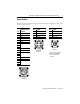
MP-Series Integrated Gear Motor Installation Instructions 9 Connector Data The tables below list the signal descriptions for the feedback, power, and brake connector pins. Feedback Connector High Resolution Pin Encoder A Sin+ B SinC Cos+ D CosE Data+ F DataG Reserved H J K +5V dc L Common M Reserved N P R TS+ S TST Reserved U V U P V T H A A D B D B C C ITT Cannon TNM 10-4 ITT Cannon TNM 16-4 Note: Ensure that proper polarity is maintained when wiring a brake connector.
MP-Series Integrated Gear Motor Installation Instructions Mounting Dimensions Dimensions for MP-Series Integrated Gear Motors are provided on the listed pages. Refer to Figure 1 on page 11 for the dimensional symbol designations for the motors.
MP-Series Integrated Gear Motor Installation Instructions 11 Figure 1 References for Motor Mounting Dimensions L LB L-LB E T NB LA LE AE D AF AG AC N LD MPG-x025-091x22 shown DB P S (diameter of hole) M (dia. of bolt circle on motor housing) MA (thread and depth) MC (dia.
MP-Series Integrated Gear Motor Installation Instructions Motor Dimension MPG-A004-031x22 Symbol 1, 2 mm (in.) AC 70 (2.76) AD 80 (3.15) AE 75 (2.95) AF N/A AG N/A BE 67.7 (2.67) D 39.975 - 40 (1.5738) - (1.5748) DB 20 - 20.021 x 4 DP (0.7874) - (0.7882) x (0.16) DP E 3 (0.12) HD 123 (4.84) L 156.7 (5.58) L-LB 19.5 (0.77) LA 4 (0.16) LB 137.2 (5.40) LD 140.9 (5.55) LE N/A M 79 (3.11) MA on MC M5 x 7 M5 x (0.28) on 31.5 BC on (1.24) BC MB 5 - 5.012 (0.1967) - (0.1973) x 6 DP x (0.24) DP N 63.97 - 64 (2.
MP-Series Integrated Gear Motor Installation Instructions 13 Motor Dimension MPG-A004-091x22 MPG-A004-091x24 Symbol 1, 2 mm (in.) mm (in.) AC 70 (2.76) 70 (2.76) AD 80 (3.15) 79.1 (3.11) AE 75 (2.95) 75 (2.95) AF N/A N/A AG N/A N/A BE 67.7 (2.67) 88.9 (3.50) D 39.975 - 40 (1.5738) - (1.5748) 39.975 - 40 (1.5738) - (1.5748) DB 20 - 20.021 (0.7874) - (0.7882) 20 - 20.021 x 4 DP (0.7874) - (0.7882) x 4 DP x (0.16) DP x (0.16) DP E 3 (0.12) 3 (0.12) HD 123 (4.84) 122.1 (4.81) L 141.7 (5.58) 185.2 (7.
MP-Series Integrated Gear Motor Installation Instructions Motor Dimension MPG-x010-031x22 Symbol 1, 2 mm (in.) AC 95.00 (3.74) AD 82.60 (3.25) AE 83.20 (3.28) AF N/A AG N/A BE 67.70 (2.67) D 62.97 - 63 (2.4791) - (2.4803) DB 31.5 - 31.525 (1.2402) - (1.2411) x 6 DP x (0.24) DP E 6.00 (0.24) HD 141.60 (5.57) L 184.5 (7.26) L-LB 30.00 (1.18) LA 7.00 (0.28) LB 154.50 (6.08) LD 156.50 (6.16) LE N/A M 109.00 (4.29) MA on MC M6 x 10 M6 x (0.39) on 50 BC on (1.97) BC MB 6 - 6.012 (0.2362) - (0.
MP-Series Integrated Gear Motor Installation Instructions Motor Dimension MPG-x010-091x22 Symbol 1, 2 mm (in.) AC 95.00 (3.74) AD 82.60 (3.25) AE 83.20 (3.28) AF N/A AG N/A BE 67.70 (2.67) D 62.97 - 63 (2.4791) - (2.4803) DB 31.5 - 31.525 (1.2402) - (1.2411) x 6 DP x (0.24) DP E 6.00 (0.24) HD 141.60 (5.57) L 169.5 (6.67) L-LB 30.00 (1.18) LA 7.00 (0.28) LB 139.5 (5.49) LD 141.5 (5.57) LE N/A M 109.00 (4.29) MA on MC M6 x 10 M6 x (0.39) on 50 BC on (1.97) BC MB 6 - 6.012 (0.2362) - (0.2367) x 7 DP x (0.
MP-Series Integrated Gear Motor Installation Instructions Motor Dimension MPG-x025-031x22 Symbol 1, 2 mm (in.) AC 120 (4.72) AD 96.5 (3.80) AE 111.2 (4.38) AF 85 (3.35) AG 68.6 (2.70) BE 67.7 (2.67) D 79.97 - 80 (3.1484) - (3.1496) DB 40 - 40.025 x (1.5748) - (1.5758) 6 DP x (0.24) DP E 6.00 (0.24) HD 169.00 (6.65) L 222.50 (8.76) L-LB 29.00 (1.14) LA 8.00 (0.31) LB 193.50 (7.62) LD 161.00 (6.34) LE 46.50 (1.83) M 135.00 (5.31) MA on MC M6 x 12 M6 x (0.47) on 63 BC on (2.48) BC MB 6 - 6.012 (0.
MP-Series Integrated Gear Motor Installation Instructions Motor Dimension MPG-x025-091x22 Symbol 1, 2 mm (in.) AC 120 (4.72) AD 96.5 (3.80) AE 111.2 (4.38) AF 85 (3.35) AG 68.6 (2.70) BE 67.7 (2.67) D 79.97 - 80 (3.1484) - (3.1496) DB 40 - 40.025 x (1.5748) - (1.5758) 6 DP x (0.24) DP E 6 (0.24) HD 169 (6.65) L 192.5 (7.58) L-LB 29 (1.14) LA 8 (0.31) LB 163.50 (6.44) LD 131.00 (5.16) LE 46.50 (1.83) M 135.00 (5.31) MA on MC M6 x 12 M6 x (0.47) on 63 BC on (2.48) BC MB 6 - 6.012 (0.2362) - (0.
MP-Series Integrated Gear Motor Installation Instructions Motor Dimension MPG-x050-031x22 Symbol 1, 2 mm (in.) AC 152 (5.98) AD 127 (5.00) AE 171 (6.73) AF N/A AG N/A BE 67.7 (2.67) D 99.965 - 100 (3.9356) - (3.9370) DB 50 - 50.025 (1.9685) - (1.9695) x 6 DP x (0.24) DP E 6 (0.24) HD 216.2 (8.51) L 274.0 (10.79) L-LB 38 (1.50) LA 10 (0.39) LB 236 (9.29) LD 230.7 (9.08) LE N/A M 168.0 (6.61) MA on MC M8 x 15 DP on (M8 x (0.59) DP on 80 BC (3.15) BC MB 8.0 - 8.015 (0.3150) - (0.3156) x 7 DP x (0.
MP-Series Integrated Gear Motor Installation Instructions Motor Dimension MPG-x050-091x22 Symbol 1, 2 mm (in.) AC 152 (5.98) AD 116.5 (4.59) AE 150.5 (5.93) AF 86 (3.39) AG 72 (2.83) BE 67.7 (2.67) D 99.965 - 100 (3.9356) - (3.9370) DB 50 - 50.025 (1.9685) - (1.9695) x 6 DP x (0.24) DP E 6 (0.24) HD 206 (8.11) L 227 (8.94) L-LB 38 (1.50) LA 10 (0.39) LB 189 (7.44) LD 156 (6.14) LE 42 (1.65) M 168.0 (6.61) MA on MC M8 x 15 DP on M8 x (0.59) DP on 80 BC (3.15) BC MB 8.0 - 8.015 (0.3150) - (0.
MP-Series Integrated Gear Motor Installation Instructions Motor Dimension MPG-x110-031x22 Symbol 1, 2 mm (in.) AC 212 (8.35) AD 127 (5.0) AE 171 (6.73) AF N/A AG N/A BE 67.7 (2.67) D 159.96 - 160 (6.2976) - (6.2992) DB 80 - 80.03 (3.1496) - (3.1508) x 8 DP x (0.31) DP E 8 (0.31) HD 250.5 (9.86) L 300.0 (11.81) L-LB 50 (1.97) LA 12 (0.47) LB 250 (9.84) LD 244.7 (9.63) LE N/A M 233 (9.17) MA on MC M10 x 20 on (M10 x (0.79) on 125 BC (4.92) BC MB 10 - 10.015 (0.3937) - (0.3943) x 10 DP x (0.39) DP N 199.
MP-Series Integrated Gear Motor Installation Instructions Motor Dimension MPG-x110-091x22 Symbol 1, 2 mm (in.) AC 212 (8.35) AD 127 (5.0) AE 171 (6.73) AF N/A AG N/A BE 67.7 (2.67) D 159.96 - 160 (6.2976) - (6.2992) DB 80 - 80.03 x (3.1496) - (3.1508) 8 DP x (0.31) DP E 8 (0.31) HD 250.5 (9.86) L 285 (11.22) L-LB 50 (1.97) LA 12 (0.47) LB 235 (9.35) LD 229.7 (9.04) LE N/A M 233 (9.17) MA on MC M10 x 20 on (M10 x (0.79) on 125 BC (4.92) BC MB 10 - 10.015 (0.3937) - (0.3943) x 10 DP x (0.39) DP N 199.
MP-Series Integrated Gear Motor Installation Instructions Housing and Output Flange Connections The following table provides ISO 898-1 mounting bolt strength class requirements for the motor housing, and tightening torques for connecting the motor housing and the ISO 9409 compliant output flange to your assembly. Apply a high-temperature, medium-strength threadlock adhesive to the mounting bolts. IMPORTANT A loose or slipping connection will cause system instability and may damage the MP gear motor.
MP-Series Integrated Gear Motor Installation Instructions 23 Motor Load Force Ratings Motors are capable of operating with a sustained shaft load. The radial and axial load force location is shown in the figure, and maximum values for motors are in the following tables. Figure 2 Load Forces on Shaft Radial load force applied at mounting end of output flange Axial load force applied at shaft centerline The following tables represent 20,000 hour L10 bearing fatigue life at various loads and speeds.
MP-Series Integrated Gear Motor Installation Instructions Radial Load Force Ratings Motor 40 rpm 60 rpm 100 rpm 156 rpm kg (lb) kg (lb) kg (lb) kg (lb) kg (lb) MPG-A004-031 179 (393) — — 162 (356) 139 (307) 130 (286) MPG-A004-091 1 179 (393) 179 (393) — — — — — — MPG-A010-031 2 337 (743) — — 286 (631) 246 (543) — — MPG-A010-091 3 337 (743) 330 (728) — — — — — — MPG-A025-031 4 478 (1053) — — 406 (895) 342 (753) — — MPG-A025-091 5 478
MP-Series Integrated Gear Motor Installation Instructions 25 Axial Load Force Ratings (Maximum Radial Load) Motor 40 rpm 60 rpm 100 rpm 156 rpm kg (lb) kg (lb) kg (lb) kg (lb) kg (lb) MPG-A004-031 166 (366) 102 (225) — — 88 (194) 82 (180) MPG-A004-091 1 166 (366) 123 (272) — — — — — — MPG-A010-031 2 219 (483) — — 201 (443) 173 (381) — — MPG-A010-091 3 219 (483) 219 (483) — — — — — — MPG-A025-031 4 407 (897) — — 254 (559) 213 (471) — — M
MP-Series Integrated Gear Motor Installation Instructions Axial Load Force Ratings (Zero Radial Load) Motor Full rpm range kg (lb) 1 166 (366) MPG-A004-091 2 166 (366) MPG-A010-031 3 219 (483) MPG-A010-091 4 219 (483) MPG-A025-031 5 423 (933) MPG-A025-091 6 423 (933) MPG-A050-031 7 625 (1378) MPG-A050-091 8 625 (1378) 1025 (2259) MPG-A004-031 MPG-A110-031 9 MPG-A110-091 10 1025 (2259) MPG-B010-031 11 219 (483) MPG-B010-091 12 219 (483) MPG-B025-031 13 423 (933
MP-Series Integrated Gear Motor Installation Instructions 27 Holding Brake A 24V dc holding brake is an option on the MP-Series Integrated Gear Motor. The following tables provide specifications on the brake. IMPORTANT Description Type Holding Torque Ensure that proper polarity is maintained when wiring a brake connector.
MP-Series Integrated Gear Motor Installation Instructions Cables and Connector Kits Factory manufactured feedback and power cables are available in standard cable lengths. They provide environmental sealing and proper shield termination to an IP66 rating, which exceeds the MP gear motor’s IP64 rating.
MP-Series Integrated Gear Motor Installation Instructions 29 If you choose to build your own cables, the following connector kits are available for MP-Series Integrated Gear Motors. These solder-type connectors mate with the motor-mounted connectors and provide environmental sealing with shield termination. Each connector kit includes the requisite number and size of solder-type contact pins, a connector housing, and a connector backshell.
MP-Series Integrated Gear Motor Installation Instructions 30 Related Documentation The following documents contain additional information concerning related Allen-Bradley products. To obtain a copy, contact your local Rockwell Automation office or distributor, or access on-line at: www.theautomationbookstore.com or www.ab.com/manuals/gmc.
MP-Series Integrated Gear Motor Installation Instructions 31 Notes Publication MP-IN003C-EN-P — April 2003
For more information refer to our web site: www.ab.com/motion For Allen-Bradley Technical Support information refer to: www.ab.com/support or Tel: (1) 440.646.5800 Allen-Bradley is a registered trademark of Rockwell Automation, Inc. Kinetix, Ultra3000 and Ultra5000 are trademarks of Rockwell Automation, Inc. Publication MP-IN003C-EN-P — April 2003 Supersedes Publication MPG-IN003B-EN-P April 2002 PN 0013-2052-003-01 Copyright © 2003 Rockwell Automation, Inc. All rights reserved. Printed in the USA.