
Owner manual

MP-Series Food-grade Servo Motor with 100 mm to 165 mm Frame Size 17
Rockwell Automation Publication MP-IN004E-EN-P - January 2014
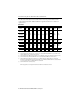
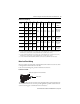
Connector Data
These tables provide the signal descriptions for the feedback, power, and brake pinouts on the
connectors.
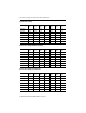
M23 Feedback and Power/Brake Pin Descriptions
Pin MPF-A3xx…MPF-A45xx Pin MPF-A3xx…MPF-A45xx, and
MPF-B3xx…MPF-B45xxx
1Sin+ A Phase U
(1)
(1) Power pins A, B, C, and D can also be labelled U, V, W, and GND respectively. Brake pins F and G can also be labelled as + and - (positive and
negative) respectively. Reserved pins E and H can also be numbered 1 and 2.
2Sin- BPhase V
(1)
3Cos+ CPhase W
(1)
4 Cos- D Ground
(1)
5 Data+ E Reserved
(1)
6Data- FMBRK+
(1)
7
Reserved
GMBRK-
(1)
8H
Reserved
(1)
9+5V DC L
10 Common
11
Reserved
12
13 TS+
14 TS-
15
Reserved 16
17
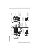
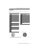
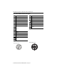
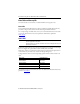
M23 Feedback Connector
M23 Power/Brake Connector
1
2
3
4
5
6
7
8
9
10
11
12
13
14
17
15
16
B C
A
G
L
F
E
H
D