
User guide


Rockwell Automation Publication MP-UM001D-EN-P - September 2013 87
Appendix D
Interconnect Diagrams
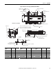
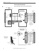
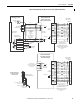
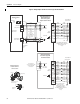
This appendix provides wiring examples to assist you in wiring an Bulletin MPAS
linear stage to a Allen-Bradley drive.
Wiring Examples
The notes below apply to the wiring examples on the pages that follow.
Not all of the notes apply to each example.
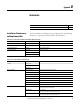
Topic Page
Wiring Examples 87
Motor/Axis Module Wiring Examples 88
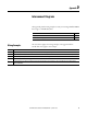
Note Information
1 Cable shield clamp must be used to meet CE requirements. No external connection to ground is required.
2 The Kinetix 2000 or Kinetix 6000 axis module referenced is either an individual axis module or the same axis module that resides within an multi-axis system.
3 For motor cable specifications, refer to the Kinetix Motion Control Accessories Technical Data, publication GMC-TD004.
4 MPAS-Axxxxxx encoders use the +5V DC supply. MPAS-Bxxxxxx encoders use +9V DC.
5 Use a flyback diode for noise suppression of the motor brake coil of an Ultra3000 drive. For more information, refer to System Design for Control of Electrical Noise,
publication GMC-RM001.