
User guide

Rockwell Automation Publication MP-UM001D-EN-P - September 2013 39
Chapter 5
Connector Data
Linear Stage Power and
Feedback Connections
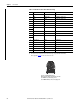
The following tables identify the power and feedback pinouts for circular
connectors for used with standard Allen-Bradley cables.
The direct drive and ball screw linear stages use different encoder types.
Consequently, the feedback connector signals are different for each of these
linear stage types.
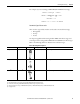
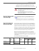
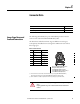
Table 3 - Power Connector
Topic Page
Linear Stage Power and Feedback Connections 39
PTC Thermal Signal 42
Pin
Color
(1)
(1) These are the wire colors for the leads on the direct drive linear stages (catalog number MPAS-xxxxxx-ALMx2C).
Wires for the ball screw linear stages (catalog number MPAS-xxxxxx-V0xxSxA) are not field accessible.
Signal
ARed U (A) Phase
B White V (B) Phase
CBlack W (C) Phase
D Green/Yellow Ground
F
White
Brake+
(2)
(2) Brake+ and Brake- are available on only the ball screw linear stages having a rotary motor with a brake.
G
Black
Brake-
(2)
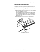
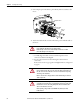
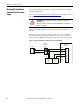
ATTENTION: Disconnect input power supply before installing or servicing
stage.
Properly ground the stage as described in both this manual and the drive
manual
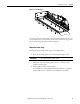
A
CB
D
E
H
L
F
Intercontec P/N BKUA145NN00480200000
Mating Allen-Bradley Power Cable
2090-CPWM7DF-16AAxx (standard) or
2090-CPWM7DF-16AFxx (continuous-flex) or
2090-CPBM7DF-16AAxx (with brake)