User Manual MP-Series Integrated Linear Stages Catalog Numbers MPAS-A6xxx1-V05SxA, MPAS-A6xxx2-V20SxA, MPAS-A8xxx1-V05SxA, MPAS-A8xxx2-V20SxA, MPAS-A9xxx1-V05SxA, MPAS-A9xxx2-V20SxA, MPAS-B6xxx1-V05SxA, MPAS-B6xxx2-V20SxA, MPAS-B8xxx1-V05SxA, MPAS-B8xxx2-V20SxA, MPAS-B9xxx1-V05SxA, MPAS-B9xxx2-V20SxA, MPAS-A6xxxB-ALMx2C, MPAS-A8xxxE-ALMx2C, MPAS-A9xxxK-ALMx2C, MPAS-B8xxxF-ALMx2C, MPAS-B9xxxL-ALMx2C
Important User Information Read this document and the documents listed in the additional resources section about installation, configuration, and operation of this equipment before you install, configure, operate, or maintain this product. Users are required to familiarize themselves with installation and wiring instructions in addition to requirements of all applicable codes, laws, and standards.
Summary of Changes This manual contains new and updated information. Changes throughout this revision are marked by change bars, as shown to the right of this paragraph. New and Updated Information This table contains the changes made to this revision.
Summary of Changes Notes: 4 Rockwell Automation Publication MP-UM001D-EN-P - September 2013
Table of Contents Preface About This Publication. . . . . . . . . . . . . . . . . . . . . . . . . . . . . . . . . . . . . . . . . . . . . 9 Who Should Use This Manual . . . . . . . . . . . . . . . . . . . . . . . . . . . . . . . . . . . . . . 9 Studio 5000 Environment . . . . . . . . . . . . . . . . . . . . . . . . . . . . . . . . . . . . . . . . . . 9 Additional Resources . . . . . . . . . . . . . . . . . . . . . . . . . . . . . . . . . . . . . . . . . . . . . 10 Chapter 1 Safety Safety Labels . . . . .
Table of Contents Chapter 5 Connector Data Linear Stage Power and Feedback Connections . . . . . . . . . . . . . . . . . . . . . 39 PTC Thermal Signal. . . . . . . . . . . . . . . . . . . . . . . . . . . . . . . . . . . . . . . . . . . . . . 42 Chapter 6 Configuration Guidelines Required Files . . . . . . . . . . . . . . . . . . . . . . . . . . . . . . . . . . . . . . . . . . . . . . . . . . . Configuring Your Linear Stage . . . . . . . . . . . . . . . . . . . . . . . . . . . . . . . . . . . .
Table of Contents Appendix B Accessories Installation, Maintenance, and Replacement Kits . . . . . . . . . . . . . . . . . . . 83 Appendix C Stacking Stages Stage Stacking . . . . . . . . . . . . . . . . . . . . . . . . . . . . . . . . . . . . . . . . . . . . . . . . . . . 85 Specifications for Stacked Stages. . . . . . . . . . . . . . . . . . . . . . . . . . . . . . . . . . . 86 Appendix D Interconnect Diagrams Wiring Examples. . . . . . . . . . . . . . . . . . . . . . . . . . . . . . . . . . . . . .
Table of Contents 8 Rockwell Automation Publication MP-UM001D-EN-P - September 2013
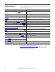
Preface Read this preface to familiarize yourself with the rest of the manual. About This Publication This manual provides detailed installation instructions for mounting, wiring, maintaining, and troubleshooting your MP-Series integrated linear stage. For ease of use, going forward, it is referred to as a linear stage. Who Should Use This Manual This manual is intended for engineers or technicians directly involved in the installation, wiring, and maintenance of linear stages.
Preface These documents contain additional information concerning related products from Rockwell Automation.. Additional Resources Resource Description Kinetix Motion Control Selection Guide, publication GMC-SG001 Provides an overview of Kinetix servo drives, motors, actuators, and motion accessories designed to help make initial decisions for the motion control products best suited for your system requirements.
Chapter 1 Safety Topic Page Safety Labels 12 Clearances 13 General Safety 13 Heat 14 Vertical or Inclined Payload 14 End of Travel Impacts 14 Air Freight Restrictions 14 Standards 15 Motor Model Identification 15 IMPORTANT Any person that teaches, operates, maintains, or repairs these linear stages must be trained and demonstrate the competence to safely perform the assigned task.
Chapter 1 Safety To prevent injury and damage to the linear stage, review the safety labels and the details and location for each table before using the linear stage. Safety Labels Location Title A Danger-Pinch Points and Heavy Objects Label Details The linear stage presents a muscle strain hazard if one person attempts to lift it. When attempting to move the linear stage use a two-person-lift to prevent personal injury or damage to the linear stage.
Safety Chapter 1 Figure 1 - Label Locations for Direct Drive Linear Stages DANGER A POINTSe PINCHparts insid Moving Lockout /Tagout Product Nameplate E ARD LIFT HAZson Lift Two Perrequired or carry MA LO GN DA NG ER CA ETI TED C Ca FIE pan be IN THLDS sencem ha IS sit akermful AR EA ive rs eq and to uip ot me he nt r DANGER OUS HAZARD VOLTAGE AND LOCKOUT POWER TAGOUT ING BEFORE C SERVIC B D F Figure 2 - Label Locations for Ball Screw Linear Stages A DANGER POINTSe PINCHparts insid Moving
Chapter 1 Safety Heat When the stage is running at its maximum rating, the temperature of the carriage can reach 75 ºC (167 ºF). Vertical or Inclined Payload A direct drive (linear motor driven) linear stage mounted vertically or on an incline does not maintain position when the power is removed. Under the influence of gravity the carriage and its payload falls to the low end of travel.
Safety Chapter 1 As a minimum, refer to the following IATA Dangerous Goods Regulations: • Subsection 1.5: Training • Subsection 3.9.2.2: Classification as Magnetized Material • Subsection 4.2: Identification as UN 2807, Magnetized Material, Class 9, Packing Instruction 902 • Subsection 7.1.5: Marking • Subsection 7.2: Labeling • Subsection 7.4.
Chapter 1 Safety Notes: 16 Rockwell Automation Publication MP-UM001D-EN-P - September 2013
Chapter 2 Understanding Your Linear Stage Topic Page Identifying Your Linear Stage 18 Identifying the Components of Your Linear Stage 19 Maintenance Intervals 22 Rockwell Automation Publication MP-UM001D-EN-P - September 2013 17
Chapter 2 Understanding Your Linear Stage Identifying Your Linear Stage Use the following key to identify your linear stage and its options. MPAS - x x xxx x - x xx x x x Cable A = No cable track module (ballscrew only) C = Cable track module with IP67 intercontec connectors (direct drive only) Brake 2 = No brake 4 = 24V DC brake (ballscrew only) Cover S = Covered with strip seals (IP30 protection) O = Open Screw Lead/Direct Drive 05 = 5.0 mm/rev (0.19 in./rev) ballscrew with rotary motor 20 = 20.
Understanding Your Linear Stage Chapter 2 Use the diagrams and descriptions to identify individual components of the linear stages. Identifying the Components of Your Linear Stage Not all components are part of the direct drive or the ball screw linear stage. For example, the direct drive linear stage does not have component 20 - Rotary Motor and the ball screw linear stage does not have component 6 - Cable Carrier Module.
Chapter 2 Understanding Your Linear Stage Figure 4 - Components of the Ball Screw Linear Stage (MPAS-xxxxxx-VxxSxA) 4 3 9 (4x) 2 (4x) 5 (2x) 7 (2x) 19 21 20 8 (4x) 1 13 (2x) 12 (4x) 18 17 16 Refer to Component Descriptions beginning on page 21 for the name and description of each numbered item.
Understanding Your Linear Stage Chapter 2 Component Descriptions Item Name Notes 1 Ground Screw and Ground Label Use the labeled M5 x 0.8 - 6H ground screw to connect the linear stage to a facility safety ground. 2 Bearing Lubrication Ports These capped ports provide access to the linear bearings without dismantling the linear stage. In addition, these tapped holes (M10 x 1.5 -6H) can be used to secure lifting hooks (not provided). . Carriage This is where your load mounts.
Chapter 2 Understanding Your Linear Stage Maintenance Intervals This section lists typical maintenance intervals for your linear stage, and references the section where maintenance procedures are described. Lubrication Intervals Refer to the Chapter 7 for lubrication procedures. The following lubrication intervals are recommended.
Chapter 3 Planning Your Installation Topic Page General Safety Standards for Linear Stage Installations 23 UL Safety Standards for Linear Stage Installations 24 Mounting Restrictions 24 Requirements to be met when mounting your linear stage include the following. General Safety Standards for Linear Stage Installations General safety standards and requirements include, but are not limited to, the following: • ANSI/RIA R15.
Chapter 3 Planning Your Installation UL Safety Standards for Linear Stage Installations All linear stage installations must follow UL 1740 - Standard for Safety for Robots and Robotic Equipment. UL 1740 covers robots and robotic equipment rated at 600V or less and intended for installation in accordance with the National Electrical Code, ANSI/NFPA 70.
Planning Your Installation • • • • • Chapter 3 Environmental Factors Mounting Surface Restrictions Mounting Orientations for Direct Drive Linear Stages Mounting Orientations for Ball Screw Linear Stages Clearance Requirements Environmental Factors Factor Applicability Temperature The linear stage does not require any special cooling considerations. Avoid mounting it near any heat generating objects, such as a heat register.
Chapter 3 Planning Your Installation Mounting Orientations for Ball Screw Linear Stages Mounting Orientation Restriction Ceiling - inverted surface A ceiling mount (inverted on a horizontal surface) must be of the covered and sealed configuration, and have a travel of 300 mm (11.8 in.) or less. Wall - horizontal A horizontal wall mount stages must be of the covered and sealed configuration. Wall - vertical or incline Vertical wall mount or inclined stages must have a brake option.
Chapter 4 Mounting and Connecting Topic Page Unpacking, Handling, and Inspection 27 Linear Stage Storage 30 Mounting the Linear Stage 30 Connecting the Linear Stage 34 About the Air Option for Ball Screw Linear Stages 37 About the Brake Option for Ball Screw Linear Stages 37 Meeting UL Installation Standards for the Linear Stage 38 IMPORTANT Unpacking, Handling, and Inspection Any person that teaches, operates, maintains, or repairs these linear stages must be trained and demonstrate th
Chapter 4 Mounting and Connecting Unpacking Procedure The following tools are recommended for unpacking the linear stage: • Utility knife • 2.5 mm, 5 mm, and 6 mm hex keys • Packing tape Unpack your linear stage by doing the following. 1. Place the carton on a flat stable surface with the tape seam side facing you. 2. Use a utility knife to score the packing tape at the edges of the carton. 3. Lift center cover to reveal the linear stage. User Manual Desiccant Packing End Caps 4.
Mounting and Connecting Chapter 4 • For stages 1 meter (39.3 in.) or longer, use support straps at the 1/4 and 3/4 length points to avoid distorting the base. Use this support system whenever the linear stage must be lifted. 1/4 1/4 End Cap 1/4 1/4 End Cap Support Straps 6. Move the linear stage to a solid support surface before removing the shipping brace. ATTENTION: The carriage is free to move once the shipping brace is removed.
Chapter 4 Mounting and Connecting Store Packaging Material Keep the carton and packing materials in case the linear stage needs to be returned for warranty service or stored for an extended period of time. 1. Tape screws and clamp hardware to the plywood board brace. 2. Put the end caps in their original positions on the center cover and place all packing material inside the carton. 3. Lightly tape carton closed and store in a dry place.
Mounting and Connecting Chapter 4 For example, if you are mounting an MPAS-B8194F-ALM02C linear stage. 1940 mm strokelength = 194.0cm 194 cm + 36 230 fasteners = -------------------------------- = --------- = 19.
Chapter 4 Mounting and Connecting Figure 8 - Through Bolt Mounting IMPORTANT Through bolt mounting is not available for the catalog number MPASx6xxxx-xxxxx (150 mm) stages. An uncovered linear stage is a good candidate for through bolt mounting. Figure 9 - Toe Clip Mounting 120 mm (4.72 in.) For covered linear stages, toe clips are the easiest method for mounting. On both sides of the base, secure a toe clip every 120 mm (4.72 in.) with a M6 SHCS as shown in Figure 9.
Mounting and Connecting Chapter 4 Figure 10 - Tee Nut Mounting T-Slots Tee nuts are used to mount the linear stage from underneath. Insert the Tee nuts every 120 mm (4.72 in.) in both T-slots on the bottom of the linear stage. Secure the Tee nuts by using M6 SHCS as shown in Figure 10. Mount the Linear Stage Follow these steps to install a linear stage on its mounting surface. 1. Be sure the mounting surface is clear of any and all foreign material. IMPORTANT Do not use abrasives to clean the surface.
Chapter 4 Mounting and Connecting ATTENTION: Do not attempt to move the linear stage by grasping the cable junction box. Moving the linear stage in this manner damages the linear stage and create a pinch or crush hazard. The junction box is attached to the carriage that is free to move. Lifting the linear stage in this manner creates uncontrolled movement of the heavy base.
Mounting and Connecting Chapter 4 Attach the Ground Strap and Interface Cables A ground strap and two cable connections are the only electrical connections necessary between the linear stage and the drive system. The flat surfaces on the power and feedback connectors must align during connection, and significant resistance must not be felt when tightening either connector. 1. For electrical safety, connect the ground screw on the chassis of the linear stage to the groundbus for your system.
Chapter 4 Mounting and Connecting 3. Form a drip loop in each cable at a point directly before it attaches to the motor. Align Flat Surfaces Power/Brake Connector Drip Loop in Cable Feedback Connector 4. Attach the feedback cable, and the combination power and brake cable to the motor. ATTENTION: Do not connect or disconnect the motor feedback cable, or the power and brake cable while power is applied to them.
Mounting and Connecting Chapter 4 c. Fully seat the feedback connector and the power/brake connector. • Hand tighten the collar of a threaded DIN (M4) connector six turns. • Hand tighten the collar of a SpeedTec (M7) connector one-quarter turn. ATTENTION: Keyed connectors must be properly aligned and hand-tightened. Improper alignment is indicated by the need for excessive force, such as the use of tools, to fully seat connectors. Connectors must be fully tightened for connector seals to be effective.
Chapter 4 Mounting and Connecting Meeting UL Installation Standards for the Linear Stage Linear stage installations must follow UL 1740 - Standard for Safety for Robots and Robotic Equipment. Refer to UL Safety Standards for Linear Stage Installations on page 24 for a brief description of this standard. ATTENTION: UL 1740 requires all linear stage installations be equipped as described below. The design, operation, and verification of this implementation is the machine builders responsibility.
Chapter 5 Connector Data Linear Stage Power and Feedback Connections Topic Page Linear Stage Power and Feedback Connections 39 PTC Thermal Signal 42 The following tables identify the power and feedback pinouts for circular connectors for used with standard Allen-Bradley cables. The direct drive and ball screw linear stages use different encoder types. Consequently, the feedback connector signals are different for each of these linear stage types.
Chapter 5 Connector Data Table 4 - Feedback Connector for Direct Drive Linear Stage Pin Signal Name Wire Color (2) Signal Description 1 AM+ Yellow A Quad B TTL - A Differential 2 AM- White/yellow A Quad B TTL - A Differential 3 BM+ Brown A Quad B TTL - B Differential 4 BM- White/Brown A Quad B TTL -B Differential 5 IM+ Violet TTL - Index Mark Differential 6 IM- White/Violet TTL - Index Mark Differential 7 Reserved — — 9 +5V DC White/Red Encoder and Hall Sensor Power 10
Connector Data Chapter 5 Table 5 - Feedback Connector for Ball Screw Linear Stage Pin Signal Name MPASAxxxxx (230V) Signal Description Signal Name MPASBxxxxx (460V) 1 Sin+ Analog Differential 1V p-p Sin+ 2 Sin- Analog Differential 1V p-p Sin- 3 Cos+ Analog Differential 1V p-p Cos+ 4 Cos- Analog Differential 1V p-p Data- 5 Data+ Serial Data Differential Signal + Data+ 6 Data- Serial Data Differential Signal - Data- 7 Reserved — Reserved 9 +5V DC 230V MPAS Encoder Power 10
Chapter 5 Connector Data PTC Thermal Signal Temperature °C (°F) Resistance in Ohms (1) Up to 100 (212) ≤ 750 Up to 105 (221) ≤ 7500 Up to 110 (230) ≥ 10,000 (1) Measure thermistor resistance in a direct drive linear stage at pins 13 and 14 on the feedback connector; see Feedback Connector for Direct Drive Linear Stage on page 40 for more information.
Chapter 6 Configuration Guidelines Required Files Topic Page Required Files 43 Configuring Your Linear Stage 43 Configuring Ultraware Software for Linear Stages with Ultra3000 Drives 53 Setting Travel Limits 55 Home to Torque Programming for Kinetix Multi-axis Drives with Linear Stages 56 Firmware revisions and software versions required to support the linear stages include the following: • RSLogix 5000 software, version 16.
Chapter 6 Configuration Guidelines The type of Allen-Bradley drive connected to the linear stage determines the configuration procedure. Refer to the following table to determine the configuration procedures to follow.
Configuration Guidelines Chapter 6 The Logix Designer application parameters provide basic setup and tuning data for MP-Series Integrated Linear Stages. • Setting Axis Properties in the Logix Designer Application provides basic drive parameters for a linear stage in a table specific to the type of linear stage, either direct drive linear or a ball screw. • Tuning Linear Stages by Using the Logix Designer Application begins on page 44.
Chapter 6 Configuration Guidelines Axis Properties Tab Parameter Entry/Selection, with applicable distance unit settings Millimeters Motor Feedback Conversion Hookup (1) Inches Feedback Type TTL with Hall Cycles 50 Per Millimeter Positioning Mode Linear Conversion Constant 200 drive counts / 1.0 mm 5080 drive counts / 1.0 in. Test Increment 70 mm, min for Ultra3000 drive 20 mm Kinetix 2000 drive 20 mm Kinetix 6000 drive 2.76 in. min for Ultra3000 drive 0.787 in. Kinetix 2000 drive 0.
Configuration Guidelines Chapter 6 Ball Screw Drive Stages Set these parameters in the appropriate Axis Properties tab of the Logix Designer application for ball screw linear stages, catalog number MPAS-xxxxxx-VxxxxA.
Chapter 6 Configuration Guidelines Axis Properties Tab Parameter Entry/Selection, with applicable distance unit settings Millimeters Homing Inches Mode Active Position 0 (or programmable) Offset 5 mm, min Sequence Torque Level-to-marker Direction Reverse Bi-directional Torque Level 50%, min Greater if the system friction, force, or weight exceeds 50% of the Continuous Force Rating at any point in the range of motion. Speed 50 mm/s 1.97 in./s Return Speed 10 mm/s 0.39 in./s 0.2 in.
Configuration Guidelines Chapter 6 2. Set the Brake Engage and the Brake Release delay times to the values listed in Brake Specifications for Ball Screw Linear Stage Motors on page 89. 3. Reduce the default Stopping Time Limit from 10 seconds to 0.5 seconds, as shown in the following display. IMPORTANT To prevent the carriage from moving, or falling when installed in a vertical orientation, the Stopping Time Limit must be set to 0.99 seconds or less. 4.
Chapter 6 Configuration Guidelines 5. On the Tune tab, click Start Tuning to access the Motion Initiation dialog box. 6. Click Yes to begin tuning the linear stage. ATTENTION: Motion occurs immediately after clicking Yes Tuning is complete when the Tune Servo dialog box appears. 7. Select Yes to exit Tuning, and display the Tune Results dialog box.
Configuration Guidelines Chapter 6 Calculate and Configure the Loop Gain IMPORTANT These Loop Gain procedures apply to only ball screw linear stages. You must calculate a position loop bandwidth based on the actual measured inertia. This is done by using the values from the Tune Results dialog box for a ball screw drive linear stage. The Tune Results dialog box above shows a default Position Loop Bandwidth of 45.14153 Hz, and a Load Inertia Ratio of 6.8707952. 1.
Chapter 6 Configuration Guidelines 3. Answer the remaining dialog boxes to apply the values. The proper Position Bandwidth results in a stable starting point from that you can adjust the gains to fit the application requirements.
Configuration Guidelines Configuring Ultraware Software for Linear Stages with Ultra3000 Drives Chapter 6 The following steps assume that the MP-Series linear stage and an Ultra3000 servo drive are installed and wired as one axis of a motion system. 1. Connect a serial cable model, catalog number 2090-DAPC-D09xx, to the CN3 connector on your Ultra3000 servo drive. 2. Apply ac input power to the Ultra3000 drive. 3.
Chapter 6 Configuration Guidelines Table 6 - Scaling Parameters Values User Unit Scaling Parameters (1) Distance Units for Ball Screw Linear Stages Millimeters Inches MPAS-xxxxxx-V05xxA MPAS-xxxxxx-V20xxA MPAS-xxxxxx-V05xxA MPAS-xxxxxx-V20xxA Velocity Label mm/s mm/s in./s in./s Velocity Scale 26214.4 6553.6 665845.76 166461.44 Position Label mm mm in. in. Position Scale 26214.4 6553.6 665845.76 166461.44 Acceleration Label mm/s/s mm/s/s in./s/s in.
Configuration Guidelines Setting Travel Limits Chapter 6 MP-Series Integrated Linear Stages are designed to use the software overtravel limits available in the Logix Designer application and Ultraware software. These Travel Limit procedures apply to both direct drive or ball screw linear stages. IMPORTANT Overtravel limits must be set according to the maximum speed of the servo drive system and the payload of the application.
Chapter 6 Configuration Guidelines Home to Torque Programming for Kinetix Multi-axis Drives with Linear Stages If you are using a Kinetix 2000 or Kinetix 6000 drive, read and apply Appendix E, Home to Torque-level Example, to your system-level program. IMPORTANT Perform Home to Torque Programming after you have tuned your drive and linear stage combination. Successfully complete tuning by performing the steps starting on page 43.
Chapter 7 Maintenance Topic Page Before You Begin 57 Recommended Maintenance Intervals 57 Bearing Lubrication 58 Strip Seal Cleaning 59 Cover Cleaning 59 IMPORTANT Any person that teaches, operates, maintains, or repairs these linear stages must be trained and demonstrate the competence to safely perform the assigned task. Use the following tools to lubricate and clean your linear stage. Before You Begin ATTENTION: Lockout and tagout input power before servicing. • 0.
Chapter 7 Maintenance Bearing Lubrication Lubricate the linear stage bearings as shown and described below. Use the MPSeries Integrated Linear Stage grease pump kit, and additional grease cartridges as necessary. Figure 12 - Direct Drive Linear Stage Lubrication Bearing Lubrication Ports (two per end cap) Figure 13 - Ball Screw Linear Stage Lubrication Ball Nut Lubrication Port (one per linear stage) Bearing Lubrication Ports (two per end cap) 1.
Maintenance Chapter 7 7. Remove the clamp. 8. Reinstall the protective caps on all the lubrication ports. Strip Seal Cleaning Clean the strip seals, if installed, by using a lint free cloth lightly saturated with isopropyl alcohol. IMPORTANT Replace the strip seal if it cannot be cleaned, or if an uneven or scored surface is detected during cleaning. A buildup of foreign material on the strip seal degrades the performance of the linear stage.
Chapter 7 Maintenance Notes: 60 Rockwell Automation Publication MP-UM001D-EN-P - September 2013
Chapter 8 Removing and Replacing Components Topic Page Before You Begin 61 Cable Carrier Assembly Removal 62 Cable Carrier Assembly Installation 62 Strip Seal Removal 63 Cover Removal 64 Cover Installation 64 Strip Seal Replacement 64 Side Cover Installation 65 Rotary Motor Replacement 66 ATTENTION: Lockout and tagout input power before servicing. ATTENTION: These procedures are not applicable to both types of linear stages.
Chapter 8 Removing and Replacing Components Cable Carrier Assembly Removal Follow these directions to remove the cable carrier assembly. TIP Mark the location of the end bracket before removing the cable carrier, this makes it easier to align it when reinstalling. 1. Remove the four pan head screws from junction box side cover. 2. Remove the two button head cap screws (BHCS) from the junction box cover. 3. Remove the junction box cover assembly.
Removing and Replacing Components Chapter 8 Align the cable carrier by using the alignment marks made when the worn cable carrier was removed. Strip Seal Removal Follow these directions to remove a strip seal. Figure 15 - Linear Stage Seal Components Strip Seal Clamp (4x) Seal Guide (4x) M3 SHCS (2 per guide) M3 SHCS (8x) IMPORTANT Stainless Steel Strip Seal (2x) Handle strip seal material with care. The strip seal has sharp edges that can cut if mishandled. 1.
Chapter 8 Removing and Replacing Components Cover Installation Follow these directions to install a cover. 1. Start at the end cap nearest the magnetic cautionary label or the MP motor, and install two M4 x 25 SHCS. 2. Torque the M4 x 25 SCHS to 4 N•m (35 lb•in). 3. Make sure the cover contacts the end cap. 4. On the opposite end install two M4 x 30 SHCS and bottom out the screw. The cover does not contact the end cap on this side and floats on the screw.
Removing and Replacing Components Chapter 8 9. Move the carriage by hand through the complete range of travel and make sure the strip seal seats smoothly against the cover and side panel magnet strips. Pulling against the tightened end clamp helps to smooth the seal. 10. Once the seal lays flat and smooth against the top cover and side panel, tighten the second end clamp. 11. With the outside edge of the end clamps as a guide, use tin snips to cut and remove excess strip seal material. 12.
Chapter 8 Removing and Replacing Components Rotary Motor Replacement Follow these directions to replace a rotary motor. 1. Disconnect the motor cables. 2. Remove the four M5 SHCS and lock washers that secure the motor to the linear stage. M4 SHCS M5 SHCS (4x) A B 3. Remove the motor. IMPORTANT Measure the position of the coupling on the motor shaft as shown in panel B of the diagram above. 4. Mark the measured coupling position on the new motor shaft. 5.
Removing and Replacing Components Chapter 8 10. Attach the power and feedback cables to the motor, by aligning the flat edges on the cable connector with those on the motor connector.
Chapter 8 Removing and Replacing Components Notes: 68 Rockwell Automation Publication MP-UM001D-EN-P - September 2013
Chapter 9 Troubleshooting This chapter is divided into three sections: • Use the diagnostic tables during axis commissioning • Use the operational section to troubleshoot either a direct drive or ball screw linear stage after the axis is up and running • Use the thermistor measurement section when direct-drive operational troubleshooting suggests Troubleshooting During Commissioning and Start-up Topic Page Troubleshooting During Commissioning and Start-up 69 Operational Troubleshooting 70 Use thi
Chapter 9 Troubleshooting Operational Troubleshooting Symptom Possible Cause Solution Linear stage, direct drive or ball screw, passes Hookup testing but the carriage jumps position when the axis is enabled. Wiring of the Hall signals with relation to the motor’s power wiring is incorrect. Verify wiring of Hall signals (S1, S2, and S3) and power wires (U, V, and W). Direct drive linear stage fails Hookup testing, but wiring is known to be correct. Incorrect drive firmware.
Troubleshooting Chapter 9 Direct Drive Linear Stage Evaluation Procedure 1. Power down the drive system. 2. Disconnect the drive from the linear stage. ATTENTION: Lockout and tagout input power before servicing the linear stage. 3. By hand, move the carriage through the entire range of motion. The carriage must move freely and smoothly. 4. If excessive resistance is felt, clean and relubricate the linear bearings. 5.
Chapter 9 Troubleshooting 5. If excessive resistance is felt, clean and relubricate the linear bearings. 6. Perform the procedures for a ball screw linear stage listed in the troubleshooting tables starting on page 72. 7. If the problem persists, return for factory evaluation and possible repair. ATTENTION: Lockout and tagout input power before servicing the linear stage.
Troubleshooting Chapter 9 Symptom Possible Cause Solution Drive reporting error E05. Defective motor Disconnect the flex cable and probe the Motor Power connector (white Mate-N-Lok) in the open Junction Box. 1. Measure the resistance between pins 1 and 2, pins 2 and 3, and pins 1 and 3, and evaluate the measurements with the following criteria: – The resistance values varies depending on the MPAS model, but must be less than 15 Ohms.
Chapter 9 Troubleshooting Notes: 74 Rockwell Automation Publication MP-UM001D-EN-P - September 2013
Appendix A Dimensions Associated Kinetix publications listed in Additional Resources on page 10 and information in product specifications can supersede the information in this appendix. Topic Page MP-Series Linear Stage Dimensions 75 MP-Series Linear Stage Dimensions Linear stages are designed to metric dimensions. Inch dimensions are conversions from millimeters. Untoleranced dimensions are for reference.
Appendix A Dimensions Figure 16 - MP-Series Linear Stages (MPAS-A/B6xxx1/2-VxxSxA) 30.5 (1.20) Mechanical Overtravel 239 (9.41) 25.0 (0.98) 165 (6.50) (4X) M6 x 1.0-6H 12.0 (0.47) 30.5 (1.20) Mechanical Overtravel 37.0 (1.46) 25.0 (0.98) 165 (6.50) 167 (6.57) (4X) Ø 7.0 (0.28) 45.0 (1.80) Thru Pilot Hole 46.8 (1.84) 181.5 (7.15) 120 (4.72) Toe Clamp/Tee Nut Spacing 54.5 (2.15) The overall length (OAL) is measured to the head of the screws that secure the motor endcap.
Dimensions Appendix A Figure 17 - MP-Series Linear Stages (MPAS-A/B8xxx1/2-VxxSxA) 25.4 (1.0) Mechanical Overtravel (4X) M8 x 1.25-6H 12.0 (0.47) (4X) Ø 6.8 (0.27) 45.2 (1.78) Thru 239 (9.41) 130.8 (5.15) Travel 44.2 (1.74) 25.4 (1.0) Detail A 25.4 (1.0) 25.4 (1.0) Mechanical Overtravel 5.22 (0.206) 216.8 (8.53) 215.7 (8.49) 6.0 (0.24) Depth, max Square Nut (2X) Ø 5.5 (0.22) Through Mount to base by using Pilot Hole M6 x 1.0 hardware (optional accessory). Dimensions are in mm (in.
Appendix A Dimensions Figure 18 - MP-Series Linear Stages (MPAS-A/B9xxx1/2-VxxSxA) 25.4 (1.0) Mechanical Overtravel 25.4 25.4 (1.0) (1.0) Detail A (4X)M8 M8xx1.25-6H 1.25-6H 12.0 12.0(0.47) (0.47) (4X) 6.8(0.27) (0.27) 45.2 (4X)ØØ6.8 45.2(1.78) (1.78)Thru Thru (4X) 239 239 (9.41) (9.41) 130.8 130.8 (5.15) (5.15) 44.2 44.2 (1.74) (1.74) 265.8 265.8 (10.46) (10.46) 264.7 264.7 (10.42) (10.42) 5.60 5.60 (0.22) (0.22) 6.5 (0.26) Depth, max (2X) Ø 5.5 (0.
Dimensions Appendix A Figure 19 - MP-Series Linear Stages (MPAS-A6xxxB-ALMx2C) 12.0 (0.47) (4X) M6 x 1.0-6H 339 (13.35) 30.5 (1.20) Mechanical Overtravel 25.0 (0.98) 30.5 (1.20) Mechanical Overtravel Travel 165 (6.50) 87.0 (3.43) 25.0 (0.98) 167 (6.57) 130 (5.12) (4X) Ø 7.0 (0.28) 45.0 (1.80) Thru Pilot Hole See Detail A 46.8 (1.84) 238.6 (9.39) 181.5 (7.15) Dimensions are in mm (in.) (4X) M10 x 1.5-6H Through (2 per end cap) Access point for lubricating linear bearings.
Appendix A Dimensions Figure 20 - MP-Series Linear Stages (MPAS-A/B8xxxx-ALMx2C) (4X) M8 x 1.25-6H 12.0 (0.47) (4X) Ø 6.8 (0.27) 45.2 (1.78) Thru (2X) Ø 5.5 (0.22) Through Pilot Hole 25.4 (1.0) Mechanical Overtravel 25.4 (1.0) 28.0 (1.10) 215.7 (8.49) 339 (13.35) 46.8 (1.84) 216.7 (8.53) 166.6 (6.56) 120 (4.72) 232 (9.13) 120 (4.72) Toe Clamp/ Square Nut Spacing 116.4 (4.58) (4X) M10 x 1.5-6H Through (2 per end cap) Access point for lubricating linear bearings.
Dimensions Appendix A Figure 21 - MP-Series Linear Stages (MPAS-A/B9xxxx-ALMx2C)s (4X) M8 x 1.25-6H 12.0 (0.47) (4X) Ø 6.8 (0.27) 45.2 (1.78) Thru (2X) Ø 5.5 (0.22) Through Pilot Hole 25.4 (1.0) Mechanical Overtravel 25.4 (1.0) 28.0 (1.10) 264.7 (10.42) 339 (13.35) 130.8 (5.15) 25.4 (1.0) 104.1 (4.10) 265.7 (10.46) 208.6 (8.21) Dimensions are in mm (in.) 46.8 (1.84) Ø 5.8 (0.23) Thru Ø 9.7 (0.38) Thru (4X) 9/16-12 UNC Through (2 per end cap) Access point for lubricating linear bearings.
Appendix A Dimensions Notes: 82 Rockwell Automation Publication MP-UM001D-EN-P - September 2013
Appendix B Accessories Topic Page Installation, Maintenance, and Replacement Kits 83 Accessories available for installing linear stages, replacing items, and performing maintenance at regular intervals are listed in the tables that follow.
Appendix B Accessories Table 13 - Accessories for Ball Screw Linear Stages (continued) Description Catalog Number Comments Side Covers Replacement Kits MPAS-6xxx1-SIDE xxx = cm stroke: 012, 018, 024, 030, 036, 042, 054, or 066 MPAS-8xxx1-SIDE xxx = cm stroke: 012, 018, 024, 030, 036, 042, 054, 066, 078, 090, or 102 MPAS-9xxx1-SIDE xxx = cm stroke: 012, 018, 024, 030, 036, 042, 054, 066, 078, 090, or 102 MPAS-6xxx1-TOP xxx = cm stroke: 012, 018, 024, 030, 036, 042, 054, or 066 MPAS-8xxx1-TOP x
Appendix C Stacking Stages This appendix provides information about center-stacked stage configurations. Stage Stacking Topic Page Stage Stacking 85 Specifications for Stacked Stages 86 Certain combinations of MPAS linear stages are designed to be stacked on top of one another. Stacking forms an X-Y axis arrangement. A center-stack arrangement mounts the top axis in the middle of the bottom axis. The top stage is centered on the bottom stage.
Appendix C Stacking Stages Specifications for Stacked Stages Linear stage specifications are based on mounting the stage to a precision base along the entire length of the stage, and stage specifications follow this convention. In the case of stacked stages, the top axis is no longer supported along its entire length, and this alters both the precision and the load carrying capability of that stage.
Appendix D Interconnect Diagrams This appendix provides wiring examples to assist you in wiring an Bulletin MPAS linear stage to a Allen-Bradley drive. Wiring Examples Topic Page Wiring Examples 87 Motor/Axis Module Wiring Examples 88 The notes below apply to the wiring examples on the pages that follow. Not all of the notes apply to each example. Note Information 1 Cable shield clamp must be used to meet CE requirements. No external connection to ground is required.
Appendix D Interconnect Diagrams Motor/Axis Module Wiring Examples Figure 23 - Wiring Examples for MP-Series Linear Stages and Kinetix 2000 Drives Cable Shield Clamp Kit KINETIX 2000 IAM (inverter) or AM MPAS-A/Bxxxx-V05SxA and MPAS-A/Bxxxx-V20Sx A Ball Screw Stages with High Resolution Feedback Note 1 0 1 2 3 4 5 6 7 8 9 10 11 12 13 14 15 Shield Motor Power (MP) Connector W V U 4 Green/ Yellow D 3 2 1 Blue C B W Black Brown A U 2090-CPWM7DF-16AAxx (standard) or 2090-CPBM7DF-16AAxx (with
Interconnect Diagrams Appendix D Figure 24 - Wiring Examples for MP-Series Linear Stages and Kinetix 6000 Drives KINETIX 6000 IAM (inverter) or AM MPAS-A/Bxxxx-V05SxA and MPAS-A/Bxxxx-V20SxA Ball Screw Stage with High Resolution Feedback Note 2 0 1 2 3 4 5 6 7 8 9 10 11 12 13 14 15 Cable Shield Clamp Shield Note 1 Motor Power (MP) Connector W V U 4 3 2 1 Motor/Resistive Brake (BC) Connector MBRK MBRK + PWR DBRK DBRK + D Blue C B W Black Brown A U 2090-CPWM7DF-16AAxx (standard) or 2090-
Appendix D Interconnect Diagrams Figure 25 - Wiring Examples for MP-Series Linear Stages and Ultra3000 Drives Ultra3000 Digital Servo Drive MPAS-A/BxxxxV05SxA and MPAS-A/BxxxxV20SxA Ball Screw Stage with High Resolution Feedback Note 2 0 1 2 3 4 5 6 7 8 9 10 11 12 13 14 15 Cable Shield Clamp Shield Note 1 Motor Power (TB1) Connector 4 3 2 1 W V U D Blue Black C B Brown A W BRK BRK+ 43 44 GND V Three-Phase U Motor Power 2090-CPWM7DF-16AAxx (standard) or 2090-CPBM7DF-16AAxx (with brake
Appendix E Home to Torque-level Example Use this appendix to become familiar with the Home to Torque-level sequence in RSLogix 5000 software, version 16.xx or later or the Logix Designer application, and the considerations required when using this homing method. This document provides an example for a typical homing program routine. The example shown does not claim to be complete and does not apply to any specific application.
Appendix E Home to Torque-level Example About Home to Torque-level Homing Home to torque-level homing is a process that references a known position by monitoring torque while driving an axis into a mechanical hard-stop. Once the actual torque level reaches or exceeds a specified torque level for a set time of 500 ms, a status flag is set in the controller. IMPORTANT Because the process of home to torque-level requires axis motion, the axis homing mode must be configured as Active.
Home to Torque-level Example Appendix E Figure 27 - Position/Velocity Diagram for Torque-level Homing Figure 28 - Position/Velocity Diagram for Torque-level - Marker Homing Rockwell Automation Publication MP-UM001D-EN-P - September 2013 93
Appendix E Home to Torque-level Example Drive Bipolar Torque Limit Adjustment When homing an axis to a mechanical hard-stop, set the Home Torque-level value above the torque value required to move the system, but low enough not to cause problems with the system mechanics. As part of the process of homing to a torque limit, limit the Peak Torque value to a level 10% above the Home Torque value to reduce the stresses on the mechanics and to eliminate the chance of an over-current error.
Home to Torque-level Example Disable Soft Overtravel Limit Appendix E If the application requires the use of soft-overtravel limits (Limits tab) to safeguard the system mechanics, disable the Soft Travel Limits for the axis to home. The Soft Travel Limits are disabled to prevent an error from occurring during the homing operation, but re-enable them after homing completes.
Appendix E Home to Torque-level Example Figure 30 - Axis Properties - Homing Tab Figure 31 - Axis Properties - Limits Tab 96 Rockwell Automation Publication MP-UM001D-EN-P - September 2013
Home to Torque-level Example Appendix E 3 2 1 0 Figure 32 - Ladder Code Example Rockwell Automation Publication MP-UM001D-EN-P - September 2013 97
Appendix E Home to Torque-level Example 98 Rockwell Automation Publication MP-UM001D-EN-P - September 2013 6 5 4 Figure 33 - Ladder Code Example, continued
Home to Torque-level Example Appendix E Rockwell Automation Publication MP-UM001D-EN-P - September 2013 9 8 7 Figure 34 - Ladder Code Example, continued 99
Appendix E Home to Torque-level Example 100 11 10 Figure 35 - Ladder Code Example, continued Rockwell Automation Publication MP-UM001D-EN-P - September 2013
Home to Torque-level Example Appendix E Rockwell Automation Publication MP-UM001D-EN-P - September 2013 (End) 14 13 12 Figure 36 - Ladder Code Example, continued 101
Appendix E Home to Torque-level Example Potential for Position Error When executing a torque limit homing procedure there is potential for a position error. As mentioned earlier, for the home to torque limit to complete, the output torque to the motor must reach or exceed the specified torque level for a set time of 500 ms. During this time the axis is against the mechanical hard-stop, and following error is increasing in the position loop.
Appendix F Mounting Bolts and Torque Values This appendix provides typical torque values for standard and metric bolts. Topic Page Recommended Seating Torque for Metric Bolts 103 Recommended Seating Torque for Mild Steel Rb 87 or Cast Iron Rb 83 104 Recommended Seating Torque for Brass Rb 72 105 Recommended Seating Torque for Aluminum Rb 72 (2024-T4) 106 Table 18 - Recommended Seating Torque for Metric Bolts Bolt Size (Metric) (1) Pitch Plain Cadmium Plated Zinc N•m (lb•in.) N•m (lb•in.
Appendix F Mounting Bolts and Torque Values Table 19 - Recommended Seating Torque for Mild Steel Rb 87 or Cast Iron Rb 83 Bolt Size (1), (2) UNC UNF Plain Cadmium Plated Plain Cadmium Plated N•m (lb•in.) N•m (lb•in.) N•m (lb•in.) N•m (lb•in.) (3) 0.18 (1.6) (3) #0 — — 0.24 (2.1) #1 0.44 (3.89) (3) 0.53 (4.7) (3) 0.46 (4.1) (3) 0.34 (3.0) (3) #2 0.71 (6.3) (3) 0.53 (4.7) (3) 0.76 (6.8) (3) 0.58 (5.1) (3) #3 1.08 (9.6) (3) 0.81 (7.2) (3) 1.16 (10.3) (3) 0.87 (7.7) (3) #4 1.
Mounting Bolts and Torque Values Appendix F Table 20 - Recommended Seating Torque for Brass Rb 72 Bolt Size (1), (2) UNC UNF Plain Cadmium Plated Plain Cadmium Plated N•m (lb•in.) N•m (lb•in.) N•m (lb•in.) N•m (lb•in.) (3) 0.18 (1.6) (3) #0 — — 0.24 (2.1) #1 0.43(3.8) (3) 0.33 (2.9) (3) 0.46 (4.1) 0.34 (3.0) (3) #2 0.71 (6.3) (3) 0.53 (4.7) (3) 0.77 (6.8) (3) 0.58 (5.1) (3) #3 1.08 (9.6) (3) 0.81 (7.2) (3) 1.16 (10.3) (3) 0.87 (7.7) (3) #4 1.52 (13.5) (3) 1.1 (10) (3) 1.
Appendix F Mounting Bolts and Torque Values Table 21 - Recommended Seating Torque for Aluminum Rb 72 (2024-T4) Bolt Size (1), (2) UNC UNF Plain Cadmium Plated Plain Cadmium Plated N•m (lb•in.) N•m (lb•in.) N•m (lb•in.) N•m (lb•in.) #0 — — 0.24 (2.1) (3) 0.18 (1.6) (3) #1 0.44 (3.8) (3) 0.33 (2.9) (3) 0.46 (4.1) (3) 0.34 3.0v #2 0.71 (6.3) (3) 0.53 (4.7) (3) 0.77 (6.8) (3) 0.58 (5.1) (3) #3 1.08 (9.6) (3) 0.81 (7.2) (3) 1.16 (10.3) (3) 0.87 (7.7) (3) #4 1.52 (13.5) (3) 1.
Index A accessibility 25 accessories 83 cable carrier 84 coupler 83 grease cartridge 83 grease pump 83 rotary motors 83 side cover 84 strip seal 84 strip seal kit 83 tee nut 83 toe clamp 83 top cover 84 top cover kit 84 agency standards UL 1740 - industrial robot safety 38 emergency brake release 24 power enable lighting 24 air port 21 ANSI/NFPA 79 - electrical for industrial machines 23 ANSI/RIA R15.
Index stage specific 84 connector pinout feedback connector 40 power connector 39 dimensions 150 mm 79 200 mm 80 250 mm 81 lubrication interval 57 maintenance interval 57 dust 25 E emergency brake release 24, 38 encoder strip 21 end of travel impact 13 F fastener aluminum bolt torque 106 brass bolt torque 105 cast iron bolt torque 104 illustrations 31 metric bolt torque 103 mild steel bolt torque 104 tee nut 33 through bolt 32 toe clip 32 firmware revision 43 G grease cartridge 83 grease pump 83 H home
Index mounting before mounting 92 brake option 37 EMI bonding 35 fastener illustrations 31 fastener torque 34 fastener types 31 feedback cable 40, 41 ground strap 35 interface cable 35, 36 number of fasteners 30 power cable 39 pressurized air connection 37 square nuts 33 surface flatness 33 toe clips 32 mounting restrictions 24, 25, 26 mounting surface restrictions 25 O options 18 overtemperature 42 P packaging 30 pinout feedback connector 40, 41 power connector 39 power connector 39 procedures bearing l
Index stage connectors 39 cover installation 64 cover removal 63 rotary motor installation 66 side cover installation 65 side cover torque 65 side cover support 21 storage 30 standards EN60204-1 safety of electrical machines 23 storage 30 strip seal 21, 72 guide 21 installation 64 removal 63 strip seal installation 64 strip seal kit 83, 84 U unpacking 27 V vertical installation 14 vibration 25 T tee nut 83 temperature max carriage 14 operating range 25 thermistor 42 toe clamp 83 toe clip spacing 32 tool
Index Notes: Rockwell Automation Publication MP-UM001D-EN-P - September 2013 111
Rockwell Automation Support Rockwell Automation provides technical information on the Web to assist you in using its products. At http://www.rockwellautomation.com/support you can find technical and application notes, sample code, and links to software service packs. You can also visit our Support Center at https://rockwellautomation.custhelp.com/ for software updates, support chats and forums, technical information, FAQs, and to sign up for product notification updates.