Installation Instructions MP-Series Electric Cylinders Catalog Numbers MPAR-x1xxxB, MPAR-x1xxxE, MPAR-x2xxxC, MPAR-x2xxxF, MPAR-x3xxxE, MPAR-x3xxxH Topic Page Important User Information 2 Catalog Number Explanation 3 About the MP-Series Electric Cylinders 4 Before You Begin 5 Install the Electric Cylinder 8 Mount the Electric Cylinder 10 Change Connector Orientation 12 Dimensions 13 Connector Data 19 Commissioning 20 Maintenance 35 Troubleshooting 36 Accessories 38 Specification
MP-Series Electric Cylinders Important User Information Solid-state equipment has operational characteristics differing from those of electromechanical equipment. Safety Guidelines for the Application, Installation and Maintenance of Solid State Controls (Publication SGI-1.1 available from your local Rockwell Automation® sales office or online at http://www.rockwellautomation.com/literature/) describes some important differences between solid-state equipment and hard-wired electromechanical devices.
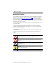
MP-Series Electric Cylinders 3 Catalog Number Explanation Catalog numbers consist of various characters, each of which identifies a specific version or option for that component. Use the catalog numbering chart below to understand the configuration of your actuator.
MP-Series Electric Cylinders About the MP-Series Electric Cylinders MP-Series electric cylinders feature multi-turn high resolution encoders and are available with 24V DC brakes. The MP-Series motor rotates a ballscrew drive that converts rotary motion into linear movement. This linear movement results in the piston rod extending and retracting from the electric cylinder housing. The MP-A/Bxxxxx-x2x electric cylinders are non-braking. When there is no input torque, the piston rod can be moved freely.
MP-Series Electric Cylinders 5 Before You Begin Remove all packing material, wedges, and braces from within and around the item. After unpacking, verify the nameplate catalog number against the purchase order. 1. Remove packaging polyethylene foil and cardboard. The packing materials are recyclable, except for oiled paper, which is waste. 2. Remove the electric cylinder carefully from its shipping container. Consider the weight of the electric cylinder.
MP-Series Electric Cylinders • Motor feedback, auxiliary feedback, and I/O connector kits are not included, but can be purchased separately. • Factory manufactured feedback and power cables are available in standard cable lengths. They provide environmental sealing and shield termination. Contact your Allen-Bradley sales office or refer to the selection guide for cables.
MP-Series Electric Cylinders 7 Preventing Electrical Noise Electromagnetic interference (EMI), commonly called electrical noise, can reduce motor performance. Effective techniques to counter EMI include filtering the AC power, using shielded cables, separating signal cables from power wiring, and practicing good grounding techniques. Follow these guidelines to avoid the effects of EMI: • Isolate the power transformers or install line filters on all AC input power lines.
MP-Series Electric Cylinders Install the Electric Cylinder The installation must comply with all local regulations and use of equipment and installation practices that promote electromagnetic compatibility and safety. ATTENTION: Unmounted electric cylinders, disconnected mechanical couplings, and disconnected cables are dangerous if power is applied. Disassembled equipment should be appropriately identified (tagged-out) and access to electrical power restricted (locked-out).
MP-Series Electric Cylinders 9 3. Attach mounting accessories to the electric cylinder; see Accessories on page 38. Tighten the fastening screws evenly. Attribute Frame 32 Frame 40 Frame 63 Internal thread of cover screws M6 M6 M8 Tightening torque, max (1) 5 N•m (3.69 lb•ft) 5 N•m (3.69 lb•ft) 9 N•m (5.90 lb•ft) (1) Unless otherwise noted, the torque value has a ±20% tolerance. 4. Attach rod-end accessories and the workload. Be sure the workload center of gravity is centric to the piston rod.
MP-Series Electric Cylinders If you are using a coupling piece attachment, catalog number MPAR-NE3612x, or trunnion mounting kit, catalog number MPAR-NA1635xx, see Accessories on page 38 for torque values. If you are using a rod guide accessory, catalog number MPAR-NE34xxx or MPAR-NE150xxx, adjust the guides of the workload and the electric cylinder so that they are exactly parallel. This avoids excessive wear on the guide. Mount the Electric Cylinder 1.
MP-Series Electric Cylinders 11 Attach Motor Cables Follow these steps to attach the power and feedback cables after the electric-cylinder is mounted. ATTENTION: Consider electric-cylinder surface temperature when selecting motor-mating connections and cables. Failure to observe these safety precautions can result in personal injury or damage to equipment. 1. Carefully align each cable connector with the respective motor connector as shown in the following diagram.
MP-Series Electric Cylinders Change Connector Orientation You can rotate the circular DIN-connector housings up to 180° in either direction. ATTENTION: You can rotate the connectors into a fixed position during installation of the electric cylinder and keep them in that position without further adjustment. Strictly limit the applied forces and the number of times the connector is rotated to be sure that connectors meet the requirements of IP66 for the motor portion of the electric cylinder.
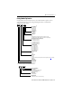
Bulletin MPAR-x1xxxx-xxB/D/E (parallel configuration) Flat for wrench. Feedback Connector 6.0 (0.24) (x4) 45.5 (1.79) 32.5 (1.28) L71 45.5 (1.79) LB Power/Brake Connector M6 (x4) 32.5 (1.28) 56.0 (2.20) 18 (0.71) 27.5 (1.08) 122+ (4.80) + 32.5 (1.28) 60 (2.36) L7 32.5 (1.28) LB Ø30.0 (1.18) d11 M10x1.25 12.0 (0.47) Ø16.0 (0.63) h9 + = Plus Stroke Length LE Dimensions are in mm (in.). MPAR-x1xxxx-xxD 26 (1.02) 66.5 (2.62) MPAR-x1xxxx-xxB 148 ±1.0 + (5.83 ± 0.04)+ 24 (0.
MP-Series Electric Cylinders MP-Series Electric Cylinder Dimensions (in-line configuration, frame 32) Electric Cylinder Cat. No. L7(1) mm (in.) MPAR-x1100B-V2A 445.7 (17.55) MPAR-x1200B-V2A 545.7 (21.48) MPAR-x1300B-V2A 645.7 (25.42) MPAR-x1400B-V2A 745.7 (29.36) MPAR-x1100E-V2A 470.7 (18.53) MPAR-x1200E-V2A 570.7 (22.47) MPAR-x1300E-V2A 670.7 (26.41) MPAR-x1400E-V2A 770.7 (30.34) LB (1) mm (in.) LE (2) mm (in.) 126.5 (4.98) 52.4 (2.06) 151.5 (5.96) 77.2 (3.
Bulletin MPAR-x2xxxx-xxB/D/E (parallel configuration) L71 54 (2.12) Flat for wrench. Feedback Connector 6.0 (0.24) (x4) 54 (2.12) 38 (1.50) LB Power/Brake Connector M6 (x4) 38 (1.50) MP-Series Electric Cylinders (frame 40) LC 24 (0.94) HC 21.5 (0.85) C GC 146.5+ (5.77) + L7 38 (1.50) PW 38 (1.50) AD MPAR-x2xxxx-xxD 30 (1.18) MPAR-x2xxxx-xxB 176.5 ± 1.0 + (6.95 ± 0.04) + 28.5 (1.12) 10.5 (0.413) 30 (1.
MP-Series Electric Cylinders MP-Series Electric Cylinder Dimensions (in-line, frame 40) Electric Cylinder Cat. No. L7 (1) mm (in.) MPAR-x2100C-V2A 501.2 (19.73) MPAR-x2200C-V2A 601.2 (23.67) MPAR-x2300C-V2A 701.2 (27.61) MPAR-x2400C-V2A 801.2 (31.54) MPAR-x2600C-V2A 1001.2 (39.42) MPAR-x2100F-V2A 492.1 (19.37) MPAR-x2200F-V2A 592.1 (23.31) MPAR-x2300F-V2A 692.1 (27.25) MPAR-x2400F-V2A 792.1 (31.19) MPAR-x2600F-V2A 992.1 (39.06) LB (1) mm (in.) LE (2) mm (in.) 151.5 (5.96) 77.
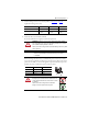
Bulletin MPAR-x3xxxx-xxB/D/E (parallel configuration) L71 75.5 (2.97) Flat for wrench. Feedback Connector 6.0 (0.24) (x4) 75.5 (2.97) 56.5 (2.22) LB Power/Brake Connector M6 (x4) 56.5 (2.22) 82 (3.23) MP-Series Electric Cylinders (frame 63) 45 (1.77) 177+ (6.97) + 56.5 (22.2) 110 (4.33) AD L7 MPAR-x3xxxx-xxD 36 (1.42) 56.5 (22.2) MPAR-x3xxxx-xxB 214 ± 1.0 + (8.42 ± 0.04) + 34 (1.34) 15 (0.59) 37 (1.46) MPAR-x3xxxx-xxE 120 ±1.0 (4.72 ± 0.04) 255 (10.04) 32 (1.26) 28.5 (1.
MP-Series Electric Cylinders MP-Series Electric Cylinder Dimensions (in-line, frame 63) Electric Cylinder Cat. No. L7 (1) mm (in.) MPAR-x3100E-M2A 603.8 (23.77) MPAR-x3200E-M2A 703.8 (27.71) MPAR-x3300E-M2A 803.8 (31.65) MPAR-x3400E-M2A 903.8 (35.58) MPAR-x3600E-M2A 1103.8 (43.46) MPAR-x3800E-M2A 1303.8 (51.33) MPAR-x3100H-M2A 574.8 (22.63) MPAR-x3200H-M2A 674.8 (26.57) MPAR-x3300H-M2A 774.8 (30.50) MPAR-x3400H-M2A 874.8 (34.44) MPAR-x3600H-M2A 1074.8 (42.
MP-Series Electric Cylinders 19 Connector Data This table lists the signal descriptions for feedback, power, and brake connector pins on the electric cylinder.
MP-Series Electric Cylinders Mating Cables Connector Cable Type Cable Cat. No.
MP-Series Electric Cylinders 21 – use Kinetix 300 drive MotionView OnBoard web interface • Kinetix 350 single-axis Ethernet drives – RSLogix 5000 software, version 20.xx or later – Firmware revision 1.30 or later • Ultra™ 3000 drives – Firmware revision 1.52 or later – Motion Database (.mdb) file, dated April 2010 or later • Motion Analyzer software, version 4.7 or later Download these files from http://www.rockwellautomation.com/support.
MP-Series Electric Cylinders Configure Your Electric Cylinder with RSLogix 5000 Software Use the following procedure to configure the drive for your electric-cylinder. The procedure assumes the electric-cylinder and the Kinetix 350, Kinetix 2000, Kinetix 6000, Kinetix 6200, or Kinetix 6500 servo drive are installed and wired as one axis of the motion system. ATTENTION: Incorrect parameter settings may result in uncontrolled motion with the potential for damage to the electric cylinder.
MP-Series Electric Cylinders 23 Axis Properties Tab Parameter Entry/Selection (with applicable distance unit settings) Conversion Positioning Mode Linear Setting the Positioning Mode to Rotary can cause damage to the electric cylinder or the machine due to incorrect positioning Conversion Constant 66666.667 drive cnts/1.0 mm for Metric English 1693333.3 drive cnts/1.0 in. for MPAR-x1xxxB-V2x MPAR-xI1xxxB-V4x Conversion Constant 20000 drive cnts/1.0 mm for 508000 drive cnts/1.0 in.
MP-Series Electric Cylinders 2. Click the Homing tab. 3. Set parameters for either absolute homing or torque level-to-marker homing as shown on this table.
MP-Series Electric Cylinders 25 7. Set overtravel limits according to the maximum speed of the servo drive system and the payload of the application. IMPORTANT Set travel limits and direction of tuning moves in reference to piston-rod starting position. Leave adequate travel for the piston rod to complete its moves while tuning. ATTENTION: Software overtravel must be set prior to initiating the tuning process. Check the starting position of the piston rod and allow for adequate travel.
MP-Series Electric Cylinders Maximum Velocity for End-stop Impact with No Load (continued) Cat. No. Extended Mass g (oz) Impact Velocity, max mm/s (in/s) MPAR-x1400E-xxx 476 (16.8) 20.5 (0.81) MPAR-x2100C-xxx 399 (14.1) 31.7 (1.25) MPAR-x2200C-xxx 488 (17.2) 28.6 (1.12) MPAR-x2300C-xxx 577 (20.4) 26.3 (1.03) MPAR-x2400C-xxx 666 (23.5) 24.5 (0.96) MPAR-x2600C-xxx 844 (29.8) 21.8 (0.86) MPAR-x2100F-xxx 469 (16.5) 29.2 (1.15) MPAR-x2200F-xxx 558 (19.7) 26.8 (1.
MP-Series Electric Cylinders 27 Tune Your Electric Cylinder with RSLogix 5000 Software This section shows the steps to tune electric cylinders with RSLogix 5000 software, version 16: • Tuning your electric cylinder requires you to calculate and configure the loop gain based on the actual measured inertia. • By setting travel limits, your application minimum deceleration is defined. Follow these steps to tune your electric cylinder. 1. In the Axis Properties dialog box, click the Fault Actions tab. 2.
MP-Series Electric Cylinders 5. Click the Tune tab and enter these parameters: • Travel Limit - Set to within software limits • Speed (velocity) • Torque/Force IMPORTANT Set travel limits and direction of tuning moves in reference to the piston-rod starting position. Leave adequate travel for the piston rod to complete its moves while tuning. ATTENTION: Software overtravel must be set prior to initiating the tuning process. Check the piston-rod starting position and allow for adequate travel.
MP-Series Electric Cylinders 29 7. Click Yes to begin tuning the electric cylinder. ATTENTION: Motion occurs immediately after clicking Yes. Tuning is complete when the Tune Servo dialog box opens. 8. Click OK to exit Tuning. The Tune Results dialog box opens. 9. If you are satisfied with the tuning results, click OK; otherwise, continue with Calculate and Configure the Loop Gain.
MP-Series Electric Cylinders Calculate and Configure the Loop Gain Calculate a position loop bandwidth based on the actual measured inertia values from the Tune Results dialog box. In this example, the Tune Results dialog box shows a default Position Loop Bandwidth of 45.14153 Hz and a Load Inertia Ratio of 6.8707952. 1. Calculate the Corrected Position Bandwidth. Corrected Position Loop Bandwidth = (Initial Position Loop Bandwidth Result/(Initial Load Inertia Ratio Result +1) For example, 5.73532 = 45.
MP-Series Electric Cylinders 31 2. Apply AC input power to the Ultra3000 drive. When communication with the Ultra3000 drive is established, the Ultra3000 Motor Database dialog box opens. 3. Click Cancel. Ultraware software begins scanning for online drives. When a drive is found, an Online Drive icon opens in the Workspace. 4. Double-click the Online Drive icon to view the main Drive Set-up dialog box. 5. Verify that the data in the Model Field is correct for your electric cylinder. 6.
MP-Series Electric Cylinders Configure the Kinetix 300 Drive for Electric Cylinders These steps assume that an electric cylinder and the Kinetix 300 drive are installed and wired as one axis of a motion system. For help using the Kinetix 300 drive as it applies to setting up your electric cylinder, refer to Additional Resources on page 47. This procedure assumes that you are familiar with the Kinetix 300 drive. 1. Run MotionView Onboard software. 2. From the Drive Organizer, click Motor. 3.
MP-Series Electric Cylinders 33 11. Enter values from the following table. These values are recommended; your application may require different values. Parameter Metric English Home Accel/Decel 10.0000 mm/s2 0.3937 in/s2 Home Offset 0.0000 mm 0.0000 in. Home Velocity Fast 10.0000 mm/s 0.3937 in/s Home Velocity Slow 10.0000 mm/s 0.3937 in/s Home Switch Input B1 12. Select recommend homing method ID = 33, Home to marker, Reverse. 13.
MP-Series Electric Cylinders You can determine the deceleration distance before the piston rod contacts the end of travel based on the deceleration rate of the load, and the peak force available from the motor/screw combination. Use Motion Analyzer software to calculate the minimum deceleration distance at the maximum speed of your application. IMPORTANT A positive-direction move command denotes a rod extend operation, a negative-direction move command denotes a retract operation.
MP-Series Electric Cylinders 35 Maintenance Follow these steps to maintain your electric cylinder. 1. Remove power to the electric cylinder and lock-out tag-out the power source. 2. Check the axial play of the piston rod for wear of the spindle nut. Wear on the electric cylinder leads to increased noise. ATTENTION: If a worn spindle nut breaks on a vertically- or diagonally-mounted electric cylinder, the workload will fall. Uncontrolled moving mass can cause personal injury or damage to equipment. 3.
MP-Series Electric Cylinders Troubleshooting This table describes some possible anomalies and steps you can take to correct them. Troubleshooting Description Possible Cause Axial play too large. Wear. Corrective Action Replace actuator cylinder. Send to Rockwell Automation for repair. Check the electric cylinder is free of stress and evenly supported 0.2 mm (0.008 in.). Distortions. Lubricate piston rod. See Maintenance on page 35. Modify positioning speed. Squeaking noises or vibrations.
MP-Series Electric Cylinders 37 Troubleshooting (continued) Description Possible Cause Corrective Action Electric cylinder is enabled but not operating or is operating erratically. Feedback cable may be damaged. Test the feedback cable. Feedback wiring may be incorrect. Verify correct feedback wiring. Motor phases are wired incorrectly or in incorrect order. Verify correct motor power wiring. Amplifier may be improperly tuned. Check gain settings.
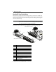
MP-Series Electric Cylinders Accessories The following diagram and tables show the available accessories and their weights. Refer to the Kinetix Motion Control Selection Guide, publication GMC-SG001, for dimensions. 1 2 4 7 3 6 5 9 8 11 10 13 12 11 17 4 14 19 16 18 20 21 9 15 1 22 2 3 4 1 2 3 Foot mount attachment Flange mounting Trunnion flange Cat. No. Weight, approx. g (oz) 32 MPAR-NP174369 140 (4.94) 40 MPAR-NP174370 280 (9.87) 63 MPAR-NP174372 550 (19.
MP-Series Electric Cylinders 39 4 5 7 9 11 12 13 15 Trunnion support Swivel flange (pin, narrow) Clevis foot (weld-on) Clevis foot (pin) Swivel flange (pin, wide) Clevis foot Clevis foot (spherical bearing) Foot mounting kit Cat. No. Weight, approx. g (oz) 32 MPAR-NA32959 130 (4.58) 40 MPAR-NA32960 400 (14.11) 63 MPAR-NA32961 480 (16.93) 32 MPAR-NP174383 90 (3.17) 40 MPAR-NP174384 120 (4.23) 63 MPAR-NP174386 320 (11.29) 32 MPAR-NP31747 105 (3.
MP-Series Electric Cylinders 17 18 19 21 Rod eye Rod clevis (threaded rod) Rod clevis (corrosion resistant) Self-aligning rod coupler Cat. No. Weight, approx. g (oz) 32 MPAR-NE9261 70 (2.47) 40 MPAR-NE9262 110 (3.53) 63 MPAR-NE9263 210 (7.41) 32 MPAR-NE32954 140 (4.94) 40 MPAR-NE10767 210 (7.41) Accessory Item 17 19 Rod eye (corrosion resistant) Rod clevis Frame Accessory Item Frame MP-Series Electric Cylinders Rod-end Accessories Cat. No. Weight, approx.
MP-Series Electric Cylinders 41 Trunnion Mounting Kit Cat. No. MPAR-NA163525 Frame Size N•m (lb•ft) Torque 32 4…5 (2.9…3.7) MPAR-NA163526 40 8…9 (5.9…6.6) MPAR-NA163528 63 18…20 (13.3…14.5) Coupling Piece Attachment Cat. No. Frame Size Max Torque (1) N•m (lb•ft) Max Torque (2) N•m (lb•ft) Max Torque (3) N•m (lb•ft) MPAR-NE36125 32 5.9 (4.35) 34 (25.1) 12 (8.8) MPAR-NE36126 40 5.9 (4.35) 61 (45.0) 22 (16.2) MPAR-NE36127 63 9.9 (7.3) 148 (109.2) 57 (42.
MP-Series Electric Cylinders Specifications Brake Specifications Electric Cylinder Cat. No. Holding Force Coil Current at 24V DC N (lb) A Release (1) ms 23 Engage (using external arc-suppression device) MOV (2) ms Diode (3) ms 9 18 MPAR-A/B1xxxB 300 (67) MPAR-A/B1xxxE 350 (79) MPAR-A/B2xxxC 525 (118) MPAR-A/B2xxxF 800 (180) 0.46…0.56 58 20 42 MPAR-A/B3xxxE 2364 (531) 0.45…0.55 50 20 110 MPAR-A/B3xxxH 1625 (365) 0.576…0.704 110 25 160 (1) 0.43…0.
MP-Series Electric Cylinders 43 Electric Cylinders (weight of cylinder with non-brake motor) Electric Cylinder Cat. No. Weight, approx. (1) kg (lb) Electric Cylinder Cat. No. Weight, approx. kg (lb) MPAR-x1100B-V2A 2.6 (5.73) MPAR-x2100C-V2A 3.7 (8.16) (1) (1) Electric Cylinder Cat. No. Weight, approx. kg (lb) MPAR-x3100E-M2A 9.5 (20.94) (3) MPAR-x3100E-M2B/D/E 13.6 (29.98) (3) MPAR-x1100B-V2B/D/E 3.5 (7.72) MPAR-x2100C-V2B/D/E 4.4 (9.70) MPAR-x1200B-V2A 2.9 (6.39) MPAR-x2200C-V2A 4.
MP-Series Electric Cylinders Interconnect Diagrams These are example diagrams for wiring your MP-Series electric cylinder and Allen-Bradley servo drives.
MP-Series Electric Cylinders 45 Wiring Example of MP-Series Electric Cylinder to Kinetix 300 Drive Kinetix 300 Drive 0 1 2 3 4 5 6 7 8 9 10 11 12 13 14 15 Motor Power (MP) Connector MP-Series Electric Cylinder 2090-XXNPMF-xxSxx Motor Power Cable Shield Green/Yellow Blue Black Brown W V U Motor Feedback (MF) Connector Three-phase Motor Power D C B A W V U GND Motor Feedback Motor Feedback (MF) Connector Thermostat Black White I/O (IOD) Connector OUT4-E OUT4-C CR1 G F BR- Black WHT/Black 1 2
MP-Series Electric Cylinders Wiring Example of MP-Series Electric Cylinder to Ultra3000 Drive Ultra3000 Drive 0 1 2 3 4 5 6 7 8 9 10 11 12 13 14 15 MP-Series Electric Cylinder 2090-XXNPMF-xxSxx Motor Power Cable Cable Shield Clamp Motor Power (TB1) Connector Motor Feedback (CN2) Connector Shield Green/Yellow Blue Black Brown W V U D C B A W GND V Three-phase Motor Power U Motor Feedback (CN2) Connector Motor Feedback Thermostat Control Interface (CN1) Connector BRK BRK+ 43 Black White 44
MP-Series Electric Cylinders 47 Additional Resources These documents contain additional information concerning related Rockwell Automation products. Resource Description MP-Series and TL-Series Electric Cylinder Replacement Parts Installation Instructions, publication MPAR-IN002 Information on replacing actuator cylinders, motors, couplings, and belts.
Rockwell Automation Support Rockwell Automation provides technical information on the Web to assist you in using its products. At http://www.rockwellautomation.com/support, you can find technical manuals, technical and application notes, sample code and links to software service packs, and a MySupport feature that you can customize to make the best use of these tools. You can also visit our Knowledgebase at http://www.rockwellautomation.