
Manual

MP-Series Heavy Duty Electric Cylinders 29
Rockwell Automation Publication MPAI-IN001E-EN-P - March 2012
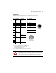
Connector Data
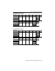
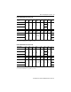
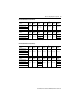
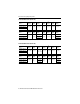
This table lists the signal descriptions for connector pins on the electric cylinder.
Feedback Power and Brake
Pin Signal Name
MPAI-Axxxxx
(230V)
Signal Name
MPAI-Bxxxxx
(460V)
Pin Signal Name
1Sin+ Sin+ A
(2)
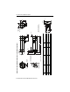
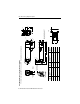
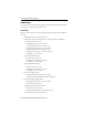
(2) Power pins A, B, C, and D may be labeled as U, V, W, and GND respectively.
Brake pins F and G brake may be labeled as + and - respectively.
Reserved pins E and H may be numbered 1 or 2.
Phase U
2Sin- Sin- B
(2)
Phase V
3 Cos+ Cos+ C
(2)
Phase W
4 Cos- Cos- D
(2)
Ground
5Data+ Data+ E
(2)
Reserved
6Data- Data- F
(2)
MBRK+
(3)
(3) Brake signals (MBRK+ and MBRK-) are available only on electric cylinders with a brake.
7 Reserved Reserved G
(2)
MBRK-
(3)
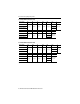
8HReserved
9+5VDC L
10 Common Case Cable Shield and GND
11 Reserved +9V DC
12 Common
13 TS+
(1)
(1) The normally closed thermal switch opens at 100 °C (212 °F).
TS+
(1)
14 TS-
(1)
TS-
(1)
15 Reserved Reserved
16
17
Case Shield Shield
ATTENTION: Be sure that cables are installed and restrained to prevent uneven tension or
flexing at the cable connectors. Excessive and uneven lateral force at the cable connector may
result in damage to the housing and contacts as the cable flexes.
Failure to observe these safety precautions could result in damage to the motor and its
components.
A
CB
D
E
H
L
F
G
Intercontec P/N
BEDC091NN00000202000
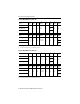
1
2
3
4
5
6
7
8
9
10
11
12
13
1415
16
17
Intercontec P/N
AEDC113NN00000202000