
Manual


10 MP-Series Heavy Duty Electric Cylinders
Rockwell Automation Publication MPAI-IN001E-EN-P - March 2012
3. Attach mounting accessories, shown on page
53, to the electric cylinder.
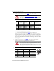
Use these torque values to attach mounting accessories to the cylinder.
If desired, you may seal the actuator front flange to the drive equipment by applying a
bead of food grade RTV around the periphery of the join between the actuator and the
machine surface. Use of a gasket or RTV on the mating surface is not recommended, as
this can cause the misalignment of the shaft and result in damage to the actuator and the
driven equipment.
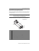
4. Attach rod-end accessories, see on page
54, to the work load as outlined below.
Be sure the work load center of gravity is centric to the thrust rod.
5. Use these torque values to attach a rod eye or rod clevis to the thrust rod.
ATTENTION: Proper attachment of the rear clevis mount is important to achieving an
IP67 rating. Refer to Installing the Rear Clevis Mounting Kit on page 12.
Failure to observe precautionary steps could result in damage to the electric cylinder
and its components.
Frame
Size
Mounting Plates Front Flange
Rear Clevis
(1)
(1) Rear clevis requires removal of the end cap from the electric cylinder. If the cylinder is opened, take precautions to avoid
contamination and then reseal the cylinder so an IP67 rating is achieved.
Torque, max
(2)
(3)
(2) Unless otherwise noted, torque specifications have a ±20% tolerance.
(3) The anti-rotation guide is not included in this step. Refer to page
11 for anti-rotation guide torque values.
64 MPAI-NA206 MPAI-NA202 MPAI-NA203 13.2 N•m (117 lb•in)
83 MPAI-NA306 MPAI-NA302 MPAI-NA303
39.5 N•m (29.1 lb•ft)
110 MPAI-NA406 MPAI-NA402 MPAI-NA403
144 MPAI-NA506 MPAI-NA502 MPAI-NA503 56.5 N•m (41.7 lb•ft)
ATTENTION: Damage may occur to the electric cylinder bearings and the feedback
device if sharp impact to the thrust rod is applied during installation. Do not strike the
thrust rod with tools during installation or removal.
Failure to observe these safety precautions could result in damage to the electric cylinder
and its components.
Frame
Size
Thrust Rod
Thread
Wrench Flats Width Torque, max
(1)
(1) Unless otherwise noted, torque specifications have a ±20% tolerance.
64 M10 x 1.25 22.99 mm (.905 in.) 24.4 N•m (18.0 lb•ft)
83 M16 x 1.5 26.97 mm (1.062 in.) 61.0 N•m (45.0 lb•ft)
110 M20 x 1.5 38.08 mm (1.489 in.) 76.3 N•m (56.3 lb•ft)
114 M27 x 2.0 53.98 mm (2.125 in.) 135.6 N•m (100.0 lb•ft)
Wrench
Flats