Installation Instructions MP-Series Heavy Duty Electric Cylinders Catalog Numbers MPAI-A2xxxC, MPAI-B2xxxC, MPAI-A3xxxC, MPAI-B3xxxC, MPAI-A3xxxE, MPAI-B3xxxE, MPAI-A3xxxR, MPAI-B3xxxR, MPAI-A3xxxS, MPAI-B3xxxS, MPAI-A4xxxC, MPAI-B4xxxC, MPAI-A4xxxE, MPAI-B4xxxE, MPAI-A4xxxR, MPAI-B4xxxR, MPAI-A4xxxS, MPAI-B4xxxS MPAI-A5xxxC, MPAI-B5xxxC, MPAI-A5xxxE, MPAI-B5xxxE Topic Page Important User Information 2 Catalog Number Explanation 3 About the MP-Series Heavy Duty Electric Cylinders 5 Before You Begin
MP-Series Heavy Duty Electric Cylinders Important User Information Solid state equipment has operational characteristics differing from those of electromechanical equipment. Safety Guidelines for the Application, Installation and Maintenance of Solid State Controls, publication SGI-1.1, available from your local Rockwell Automation® sales office or online at http://www.rockwellautomation.
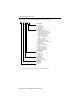
MP-Series Heavy Duty Electric Cylinders 3 Catalog Number Explanation This is the catalog explanation for the MPAI electric cylinders.
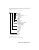
MP-Series Heavy Duty Electric Cylinders This is the catalog explanation for the MPAI electric cylinder accessories. MP AI - xx x xx xx Stroke Length (1) 76 = 76.2 mm (3.0 in.) 15 = 152.4 mm (6.0 in.) 30 = 304.8 mm (12.0 in.) 45 = 457.2 mm (18.0 in.
MP-Series Heavy Duty Electric Cylinders 5 About the MP-Series Heavy Duty Electric Cylinders MP-Series™ electric cylinders feature multi-turn high resolution encoders and are available with 24V DC brakes. The MP-Series motor drives a ball screw or roller screw that converts rotary motion into linear movement. The linear motion extends or retracts the thrust rod within the electric cylinder housing. The MP-A/Bxxxxxx2x electric cylinders are non-braking.
MP-Series Heavy Duty Electric Cylinders Before You Begin Remove all packing materials from within and around the item. After unpacking, verify the nameplate catalog number against the purchase order. 1. Remove the polyethylene foam cushioning. 2. Remove the electric cylinder carefully from its shipping container. Consider the weight of the electric cylinder. Depending on the design, the electric cylinder can weigh up to 49 kg (108 lb). Do not rotate the thrust rod.
MP-Series Heavy Duty Electric Cylinders 7 • If you are mounting your electric cylinder in a vertical or sloping position, include safety measures that will control the work load, should the spindle nut fail. ATTENTION: Uncontrolled moving masses can cause injury or damage to property. If there is a spindle nut fracture inside the actuator cylinder due to wear, the working mass will drop down.
MP-Series Heavy Duty Electric Cylinders Electric Cylinders with Brake Option The brake option on this servo motor is a spring-set holding brake that releases when voltage is applied to the brake coil. A separate power source is required to disengage the brake. This power source can be applied by a servo motor controller or manual operator control. If system main power fails, holding brakes can withstand occasional use as stopping brakes.
MP-Series Heavy Duty Electric Cylinders 9 Build and Route Cables Knowledgeable cable routing and careful cable construction improves system electromagnetic compatibility (EMC). To build and install cables, perform these steps. 1. Keep wire lengths as short as physically possible. 2. Route signal cables (encoder or serial) away from motor and power wiring. 3. Separate cables by 0.3 m (1 ft) minimum for every 9 m (30 ft) of parallel run. 4.
MP-Series Heavy Duty Electric Cylinders 3. Attach mounting accessories, shown on page 53, to the electric cylinder. ATTENTION: Proper attachment of the rear clevis mount is important to achieving an IP67 rating. Refer to Installing the Rear Clevis Mounting Kit on page 12. Failure to observe precautionary steps could result in damage to the electric cylinder and its components. Use these torque values to attach mounting accessories to the cylinder.
MP-Series Heavy Duty Electric Cylinders 11 Use two wrenches to attach a rod-end accessory: one wrench to tighten the rod-end accessory, and the other wrench to counter act the applied torque at the thrust-rod wrench flats. ATTENTION: Do not apply torque or rotate the thrust rod itself. Rotating the thrust rod will cause the home position to be lost. 6. Use these torque values to attach an anti-rotation guide to the cylinder and the thrust rod.
MP-Series Heavy Duty Electric Cylinders Installing the Rear Clevis Mounting Kit Follow this procedure to install a rear clevis mount on an MP-Series electric cylinder. ATTENTION: Proper attachment of the rear clevis mount is important to achieving an IP67 rating. Failure to observe this procedure could result in damage to the electric cylinder and its components. 1. Prepare a contamination-free area in which to work. 2. Remove the four bolts that secure the end cap. Bolts sizes are shown here.
MP-Series Heavy Duty Electric Cylinders 13 Mount the Electric Cylinder Follow these steps to mount the electric cylinder on the machine. 1. Verify the mounting surface flatness. The mounting surface must be flat or shimmed flat to the mounting surface of the electric cylinder within 0.127 mm (0.005 in.) to avoid distortion and damage to the actuator housing. 2.
MP-Series Heavy Duty Electric Cylinders Verify Connector O-ring and Backshell Seal An O-ring on the feedback connector, and a backshell seal on the feedback and power/brake connectors are necessary to achieve the maximum environmental rating. Verify the seal and O-rings are installed as described. Location Verify Groove reserved for quick-lock plug. • An O-ring is mounted on the external surface of the feedback connector and the power/brake connector.
MP-Series Heavy Duty Electric Cylinders 15 • Hand tighten the collar of a SpeedTec (M7) connector one-quarter turn. Feedback Connector Top of connector is relative to motor orientation. Flat Surface with Logo on Top Power Connector Flat Surface with Logo on Top Drip Loop ATTENTION: Make sure cables are installed and restrained to prevent uneven tension or flexing at the cable connectors.
MP-Series Heavy Duty Electric Cylinders Change Connector Orientation You can rotate the circular DIN connector housings up to 270° in either direction. As Manufactured Front (rod side of actuator) 270° 90° Front (rod side of actuator) 180° ATTENTION: For actuators with food grade white paint, consider rerouting cables instead of rotating the connectors. Rotation of the connectors interrupts continuity of the white paint across the rotation joint.
TL (thread length) min mm (in.) M10 x 1.25 x 22.1 (0.049 x 0.87) M16 x1.5 x 34.3 (0.06 x 1.35) M20 x 1.5 x 41.4 (0.06 x 1.63) M27 x 2.0 x 45.7 (0.08 x 1.80) 64 83 110 144 See Detail A Ø 99.955…100.000 (3.9352…3.9370) Ø 71.955…72.000 (2.8328…2.8346) Ø 59.955…60.000 (2.3604…2.3622) Ø 47.955…48.000 (1.8880…1.8898) PD (pilot dia.) mm (in.) Dimensions are in mm (in.
MP-Series Heavy Duty Electric Cylinders Standard Dimensions (frame 64) Electric Cylinder Cat. No. AD mm (in.) HD mm (in.) AM mm (in.) B mm (in.) S mm (in.) G1 mm (in.) G2 (1) mm (in.) 72.8 (2.87) 104.5 (4.11) 41.9 (1.65) 34.0 (1.34) M6 x 1.0 x 9.0 (0.04 x 0.35) 28.8 (1.13) 106.9 (4.21) L3 mm (in.) L7 (1) mm (in.) M (2) mm (in.) P mm (in.) T mm (in.) TG1 mm (in.) TG2 mm (in.) WH mm (in.) 288.1 (11.34) MPAI-A/B2076CV12A MPAI-A/B2150CV32A 220.2 (8.67) 20.00 (0.787) 372.6 (14.
MP-Series Heavy Duty Electric Cylinders 19 Standard Dimensions (frame 110) Electric Cylinder Cat. No. AD mm (in.) HD mm (in.) AM mm (in.) B mm (in.) S mm (in.) G1 mm (in.) G2 (1) mm (in.) 96.3 (3.79) 151.5 (5.96) 61.3 (2.41) 50.0 (1.97) M8 x 1.25 x12 (0.05 x 0.47) 31.9 (1.25) 130.7 (5.15) L3 mm (in.) L7 (1) mm (in.) M (2) mm (in.) P mm (in.) T mm (in.) TG1 mm (in.) TG2 mm (in.) WH mm (in.) 466.6 (18.37) MPAI-A/B4150xM32A MPAI-A/B4300xM32A 447.8 (17.63) 25.0 (0.98) 600.2 (23.
Rockwell Automation Publication MPAI-IN001E-EN-P - March 2012 TL (thread length) min mm (in.) M10 x 1.25 x 22.1 (0.049 x 0.87) M16 x1.5 x 34.3 (0.06 x 1.35) M20 x 1.5 x 41.4 (0.06 x 1.63) M27 x 2.0 x 45.7 (0.08 x 1.80) 64 83 100 144 See Detail A Ø 99.955…100.000 (3.9352…3.9370) Ø 71.955…72.000 (2.8328…2.8346) Ø 59.955…60.000 (2.3604…2.3622) Ø 47.955…48.000 (1.8880…1.8898) PD (pilot dia.) mm (in.) Dimensions are in mm (in.
MP-Series Heavy Duty Electric Cylinders 21 Face Mount Dimensions (frame 64) Electric Cylinder Cat. No. AD mm (in.) AM mm (in.) G1 mm (in.) G2 (1) mm (in.) HD mm (in.) MPAI-A/B2076CV12E-W MPAI-A/B2150CV32E-W 72.8 (2.87) 42.1 (1.66) 26.9 (1.06) 104.6 (4.12) 104.5 (4.11) L3 mm (in.) TG1 mm (in.) TG2 mm (in.) WH mm (in.) 63.5 (2.5) ZJ (1) mm (in.) T mm (in.) 261.2 (10.28) 1.8 (0.07) 54.0 (2.13) 20.0 (0.79) 17.5 (0.69) MPAI-A/B2300CV32E-W (1) 362.0 (14.25) 514.4 (20.
MP-Series Heavy Duty Electric Cylinders Face Mount Dimensions (frame 110) Electric Cylinder Cat. No. AD mm (in.) AM mm (in.) G1 mm (in.) G2 (1) mm (in.) HD mm (in.) MPAI-A/B4150xM32E-W MPAI-A/B4300xM32E-W 96.3 (3.79) 61.5 (2.42) 30.0 (1.18) 130.8 (5.15) 151.5 (5.96) L3 mm (in.) TG1 mm (in.) TG2 mm (in.) WH mm (in.) 110.5 (4.35) ZJ (1) mm (in.) T mm (in.) 422.3 (16.62) 1.8 (0.07) 85.0 (3.35) 55.0 (2.17) 16.8 (0.66) MPAI-A/B4450xM32E-W (1) 619.2 (24.38) 771.6 (30.
Rockwell Automation Publication MPAI-IN001E-EN-P - March 2012 TL (thread length) min mm (in.) M10 x 1.25 x 22.1 (0.049 x 0.87) M16 x1.5 x 34.3 (0.06 x 1.35) M20 x 1.5 x 41.4 (0.06 x 1.63) M27 x 2.0 x 45.7 (0.08 x 1.80) Frame Size 64 83 110 144 Wrench Flats See Detail A for size Feedback Connector TB2 TB1 Ø 99.955…100.000 (3.9352…3.9370) Ø 71.955…72.000 (2.8328…2.8346) Ø 59.955…60.000 (2.3604…2.3622) Ø 47.955…48.000 (1.8880…1.8898) PD (pilot dia.) mm (in.) Dimensions are in mm (in.
MP-Series Heavy Duty Electric Cylinders Trunnion Mount Dimensions (frame 64) Electric Cylinder Cat. No. AD mm (in.) AM mm (in.) G1 mm (in.) G2 (1) mm (in.) HD mm (in.) 72.8 (2.87) 41.9 (1.65) 28.8 (1.13) 106.9 (4.21) 104.5 (4.11) L1 mm (in.) 364.2 (14.34) 70.00 (2.756) 15.00 (0.591) WH mm (in.) ZJ (1) mm (in.) 516.64 (20.34) MPAI-A/B2450CV32B Electric Cylinder Cat. No. M (2) mm (in.) 288.0 (11.34) MPAI-A/B2150CV32B MPAI-A/B2300CV32B L7 (1) mm (in.) L3 mm (in.) MD mm (in.
MP-Series Heavy Duty Electric Cylinders 25 Trunnion Mount Dimensions (frame 110) Electric Cylinder Cat. No. AD mm (in.) AM mm (in.) G1 mm (in.) G2 (1) mm (in.) HD mm (in.) 96.3 (3.79) 61.3 (2.41) 30.4 (1.20) 130.7 (5.15) 151.5 (5.96) L1 mm (in.) 619.0 (24.37) 127.0 (5.0) 21.0 (0.83) WH mm (in.) ZJ (1) mm (in.) 771.4 (30.37) MPAI-A/B4450xM32B Electric Cylinder Cat. No. M (2) mm (in.) 466.6 (18.37) MPAI-A/B4150xM32B MPAI-A/B4300xM32B L7 (1) mm (in.) L3 mm (in.) MD mm (in.) P mm (in.
Rockwell Automation Publication MPAI-IN001E-EN-P - March 2012 TL (thread length) min mm (in.) M10 x 1.25 x 22.1 (0.049 x 0.87) M16 x1.5 x 34.3 (0.06 x 1.35) M20 x 1.5 x 41.4 (0.06 x 1.63) M27 x 2.0 x 45.7 (0.08 x 1.80) 64 83 110 144 100.0 (3.94) Ø 72.0 (2.83) Ø 60.0 (2.36) Ø 48.0 (1.89) PD mm (in.) Grease Fitting 1/4-28 thread (not present on MPAI-x2xxx) Feedback Connector Frame Size Flat for Wrench See Detail A Power/Brake Connector L3 WH AM L7 53.73…53.98 (2.115…2.125) 34.73…34.98 (1.
MP-Series Heavy Duty Electric Cylinders 27 Clevis Mount Dimensions (frame 64) Electric Cylinder Cat. No. AD mm (in.) AM mm (in.) ØD mm (in.) G1 mm (in.) G2 (1) mm (in.) H mm (in.) HD mm (in.) 72.8 (2.87) 41.9 (1.65) 10.01…10.02 (0.394…0.395) 26.9 (1.06) 104.6(4.12) 13.00 (0.512) 104.5 (4.11) L3 mm (in.) IN mm (in.) L7 (1) mm (in.) OT mm (in.) P mm (in.) WH mm (in.) ZJ (1) mm (in.) 1.5 (0.06) 26.3 (1.03) 46.25 (1.821) 63.5 (2.50) 17.3 (0.68) 337.4 (13.
MP-Series Heavy Duty Electric Cylinders Clevis Mount Dimensions (frame 110) Electric Cylinder Cat. No. AD mm (in.) AM mm (in.) ØD mm (in.) G1 mm (in.) G2 (1) mm (in.) H mm (in.) HD mm (in.) 96.3 (3.79) 61.3 (2.41) 16.01 (0.630) 30.0 (1.18) 130.7 (5.15) 22.0 (0.866) 151.5 (5.96) L3 mm (in.) IN mm (in.) L7 (1) mm (in.) OT mm (in.) P mm (in.) WH mm (in.) ZJ (1) mm (in.) 1.5 (0.06) 50.3 (1.98) 94.3 (3.71) 110.5 (4.35) 16.8 (0.66) 574.5 (22.
MP-Series Heavy Duty Electric Cylinders 29 Connector Data This table lists the signal descriptions for connector pins on the electric cylinder.
MP-Series Heavy Duty Electric Cylinders Commissioning This section provides guidelines for using RSLogix™ 5000 and MotionView OnBoard software to configure your electric cylinder servo drive system. Required Files Firmware revisions and software versions required to support the electric cylinders include the following: • RSLogix 5000 software, version 16.00 or later • Kinetix 2000, Kinetix 6000 multi-axis drives or Ultra™ 3000 drives with SERCOS – Firmware revision 1.
MP-Series Heavy Duty Electric Cylinders 31 Download these files from http://www.rockwellautomation.com/support. Contact Rockwell Automation Technical Support at (440) 646-5800 for assistance. Configure Your Electric Cylinder Configure the electric cylinder by using the basic parameter settings described in this section. Use the procedure appropriate for your motion axis.
MP-Series Heavy Duty Electric Cylinders 1. Enter these parameters in the Axis Properties tab of RSLogix 5000 software for your electric cylinder. Axis Properties Tab Parameter Entry/Selection Drive/Motor Motor Catalog Number Choose one from the pull-down menu.
MP-Series Heavy Duty Electric Cylinders 33 Axis Properties Tab Dynamics Parameter Maximum Speed Cat. No. Entry/Selection, with applicable distance unit settings Metric Value mm/s English Valuein/s MPAI-x2076CM1xx 304 12.0 MPAI-x2150CM3xx 304 12.0 MPAI-x2300CM3xx 304 12.0 MPAI-x3076CM1xx 305 12.0 MPAI-x3076EM1xx 620 25.2 MPAI-x3076RM1xx 305 12.0 MPAI-x3076SM1xx 610 25.2 MPAI-x3150CM3xx 279 11.0 MPAI-x3150EM3xx 559 22.0 MPAI-x3150RM3xx 279 11.0 MPAI-x3150SM3xx 559 22.
MP-Series Heavy Duty Electric Cylinders 2. Click the Homing tab. 3. Set parameters for either absolute homing or torque level-to-marker homing as shown in the table.
MP-Series Heavy Duty Electric Cylinders 35 7. Set overtravel limits according to the maximum speed of the servo drive system and the payload of the application. IMPORTANT Set travel limits and direction of tuning moves in reference to thrust rod starting position. Leave adequate travel for the thrust rod to complete its moves while tuning. ATTENTION: Software overtravel must be set prior to initiating the tuning process. Check the starting position of the thrust rod and allow for adequate travel.
MP-Series Heavy Duty Electric Cylinders Tune Your Electric Cylinder with RSLogix 5000 Software This section shows the steps to tune electric cylinders with RSLogix 5000 software. Refer to Required Files on page 30 for the version number: • Tuning your electric cylinder requires you to calculate and configure the loop gain based on the actual measured inertia. • By setting travel limits, your application minimum deceleration is defined.
MP-Series Heavy Duty Electric Cylinders 37 5. Click the Tune tab and enter these parameters: • Travel Limit - Set to within software limits • Speed (velocity) • Torque/Force IMPORTANT Set travel limits and the direction of tuning moves in reference to the thrust rod starting position. Leave adequate travel for the thrust rod to complete its moves while tuning. ATTENTION: Software overtravel must be set prior to initiating the tuning process.
MP-Series Heavy Duty Electric Cylinders 7. Click Yes to begin tuning the electric cylinder. Tuning is complete when the Tune Servo dialog box opens. 8. Click OK to exit Tuning. The Tune Results dialog box opens. 9. Click OK if you are satisfied with the tuning results; otherwise, continue with Calculate and Configure the Loop Gain. Calculate and Configure the Loop Gain Calculate a position loop bandwidth based on the actual measured inertia values from the Tune Results dialog box.
MP-Series Heavy Duty Electric Cylinders 39 2. Enter the Corrected Position Bandwidth value 5.73532 as the Position Loop Bandwidth. 3. Click OK. 4. Answer the remaining dialog boxes to apply the values. The proper Position Bandwidth results in a stable starting point, from which you can adjust the gains to fit your application requirements.
MP-Series Heavy Duty Electric Cylinders Configure Your Servo Drive with Ultraware Software These steps assume an electric cylinder and Ultra3000 drive are installed and wired as one axis of a motion system. For help using Ultraware software as it applies to setting up your electric cylinder, refer to Additional Resources on page 66. This procedure assumes you are familiar with Ultraware software. 1. Connect a serial cable, catalog number 2090-DAPC-D09xx, to the CN3 connector on your Ultra3000 drive. 2.
MP-Series Heavy Duty Electric Cylinders 41 7. Expand the Motor Encoder Units menu and enter the appropriate values from this table. Velocity, position, and acceleration counts per unit are based on the selected User Units (mm or in.). Cat. No. Screw mm/rev (in./rev) Encoder periods/rev Velocity Scale mm/s (in/s) Position Scale mm (in.) Acceleration Scale mm/s/s (in/s/s) MPAI-x2xxxC 5.0 (0.19685) 128 26214.40 (665845.76) 26214.40 (665845.76) 26214.40 (665845.76) MPAI-x3xxxC 5.0 (0.
MP-Series Heavy Duty Electric Cylinders Configure Your Kinetix 300 Servo Drive with MotionView OnBoard Use this procedure to configure your Bulletin MPAI electric cylinder with a Kinetix 300 servo drive. Refer to the Kinetix 300 EtherNet/IP Indexing Servo Drive User Manual, publication 2097-UM001, for details on using the MotionView OnBoard software. These steps assume an electric cylinder and Kinetix 300 drive are installed and wired as one axis of a motion system. 1.
MP-Series Heavy Duty Electric Cylinders 43 9. Set overtravel limits according to the maximum speed of the servo drive system and the payload of the application. IMPORTANT Set travel limits and direction of tuning moves in reference to thrust rod starting position. Leave adequate travel for the thrust rod to complete its moves while tuning. ATTENTION: Software overtravel must be set prior to initiating the tuning process. Check the starting position of the thrust rod and allow for adequate travel.
MP-Series Heavy Duty Electric Cylinders Tune Your Electric Cylinder with MotionView OnBoard Software 1. From the Drive Organizer, select General. 2. From the Drive Mode pull-down menu, choose Autotune. 3. Enable the motor. 4. From the Drive Organizer, select Dynamics. 5. Click Autotune. The Autotune dialog box opens with the default set to Velocity Tuning. 6. Check Velocity Tuning or Position Tuning or both. 7. Follow the instructions in the dialog box.
MP-Series Heavy Duty Electric Cylinders 45 Maintenance Follow these steps to maintain your electric cylinder. 1. Remove power to the electric cylinder. Lock-out and tag-out the electric cylinder at the power source. 2. Check the axial play of the thrust rod for wear of the spindle nut. Increased noise is one indicator of wear. ATTENTION: If a worn spindle nut breaks on a vertically or diagonally mounted electric cylinder, the work load will fall.
MP-Series Heavy Duty Electric Cylinders Lubrication Your electric cylinder has been lubricated at the factory and is ready for installation. Use the appropriate lubrication interval calculations listed below for schedule estimates or use Rockwell Motion Analyzer software to calculate the recommenced re-grease schedule for the electric cylinder. Lubrication kits are shown on page 59.
MP-Series Heavy Duty Electric Cylinders 47 Roller Screw Lubrication The lubrication interval (tl) of a roller screw actuator must be calculated. Factors that influence the lubrication interval include the following: • Frame Size - 83 or 110 mm (3.27 or 4.33 in.) • Screw Lead - 5.0 or 10 mm/rev (0.197 or 0.394 in.
MP-Series Heavy Duty Electric Cylinders Frame Size 83, 10 mm Roller Screw Load Correction KMPAI-x3xxxSM3xx = 0.44 (FXpeak/FXn)-0.15 Frame Size 110, 5 mm Roller Screw Load Correction KMPAI-x4xxxSM3xx = 0.26 (FXpeak/FXn)-0.15 Frame Size 110, 10 mm Roller Screw Load Correction KMPAI-x4xxxSM3xx = 0.40 (FXpeak/FXn)-0.15 3. Calculate the lubrication interval (tl) in hours. t1 = tbl x K, h Use the basic lubrication interval (tbl) and the load correction factor (K) from step 1 and step 2. 4.
MP-Series Heavy Duty Electric Cylinders 49 Lubrication Calculation Example The following is and example of lubrication interval calculation for MPAI-x3xxxRMxx electric cylinder. Operators Variable Description Fxpeak Actuator peak force Fxn Application maximum command force K Load correction factor Sco Screw static load factor tbl Basic lubrication interval Vrms RMS velocity Screw Static Load Factors Cat. No. Sco MPAI-x3xxxRM3xx 0.24 MPAI-x3xxxSM3xx 0.44 MPAI-x4xxxRM3xx 0.
MP-Series Heavy Duty Electric Cylinders Storage Store your electric cylinder for a minimal amount of time in a clean and dry location within the Environmental Specifications on page 65. Observe these conditions when storing the electric cylinder: • Be sure the equipment is in good working order before storing. Perform repairs, maintenance, and inspections before storing equipment.
MP-Series Heavy Duty Electric Cylinders 51 Troubleshooting Troubleshooting Electric Cylinders Description Possible cause Corrective action Axial play too large. Wear Squeaking noises or vibrations. Distortions • Replace actuator cylinder. • Send to Rockwell Automation for repair. • Verify the electric cylinder is free of stress and evenly supported 0.2 mm (0.008 in.). • Lubricate thrust rod. See Configure Your Kinetix 300 Servo Drive with MotionView OnBoard on page 42.
MP-Series Heavy Duty Electric Cylinders Troubleshooting Electric Cylinders (cont.) Description Possible cause Corrective action Electric cylinder is operating but is not up to rated speeds/forces. Motor phases are wired incorrectly or in incorrect order. Verify correct motor power wiring. Amplifier may be improperly tuned. Verify gain settings. Amplifier may be set up improperly for electric cylinder used.
MP-Series Heavy Duty Electric Cylinders 53 Accessories This diagram depicts the accessories available for the electric cylinders. Tables list the catalog number and weight for each accessory. Refer to the Kinetix Motion Control Selection Guide, publication GMC-SG001, for dimensions.
MP-Series Heavy Duty Electric Cylinders Anti-rotation Guide Accessory Weight, approx g (oz) Accessory Item 4 Anti-rotation guide 64 MPAI-NE20276 330 (11.6) 4 MPAI-NE20215 370 (13.1) Cat. No. Weight, approx g (oz) MPAI-NE40215 820 (28.9) MPAI-NE40230 980 (34.6) MPAI-NE40245 1130 (39.8) MPAI-NE50215 2330 (82.2) Frame Cat. No. Frame Accessory Item Anti-rotation guide 110 MPAI-NE20230 450 (15.9) MPAI-NE30276 660 (23.3) MPAI-NE30215 740 (26.1) MPAI-NE50230 2660 (93.
MP-Series Heavy Duty Electric Cylinders 55 For applications in which the load is free to rotate, Rockwell Automation offers the anti-rotation systems shown below. ATTENTION: The anti-rotation option is not a guide or support mechanism. It is intended only as an anti-rotation device.
MP-Series Heavy Duty Electric Cylinders Install the Anti-rotation Option These are the recommended tools: 4, 5, 6, and 10 mm hex keys (Allen wrenches), small dead blow hammer. ATTENTION: Improper alignment of the Anti-rotation shaft may result in binding and or side loading, which may reduce the life of the actuator. ATTENTION: Take precautions to not cause damage to the actuator’s grease zerk throughout the following process. ATTENTION: This procedure requires you to rotate the thrust rod.
MP-Series Heavy Duty Electric Cylinders 57 12. Apply medium strength thread-locker to the anti-rotate shaft fastener and assemble through the anti-rotate clamp and into the anti-rotate shaft; torque to the value shown on the table. Frame Size Torque 64 83 7.8 N•m (5.75 lb•ft) 110 144 20.3 N•m (15.0 lb•ft) 13. Torque the two bearing block fasteners as shown in the table. Frame Size Torque 64 13.2 N•m (9.7 lb•ft) 83 110 144 39.5 N•m (29.13 lb•ft) 56.5 N•m (70.0 lb•ft) 14.
MP-Series Heavy Duty Electric Cylinders MP-Series Sealing Air Pressure Kit A sealing air pressure kit (catalog number MPF-7-AIR-PURGE) is available for field installation on an M23 feedback connector. Positive air pressure supplied through the kit provides an additional level of protection against the ingress of foreign substances and moisture. The kit replaces the M23 feedback connector cap, provides a replacement O-ring, and includes installation instructions. You must supply 4 mm (5/32 in.
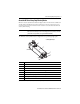
MP-Series Heavy Duty Electric Cylinders 59 Replacement Parts and Maintenance Kits 1 2 4 3 1 Item Cat. No.
MP-Series Heavy Duty Electric Cylinders Interconnect Diagrams These wiring examples are for an electric cylinder, specifically Allen-Bradley servo drives.
MP-Series Heavy Duty Electric Cylinders 61 Wiring Example of MP-Series Electric Cylinders to Kinetix 300 Drives Kinetix 300 Drive 0 1 2 3 4 5 6 7 8 9 10 11 12 13 14 15 Motor Power (MP) Connector MP-Series Electric Cylinder 2090-CPxM7DF-16AAxx, or 2090-CPxM7DF-16AFxx Power Cable Three-phase Motor Power Shield Green/Yellow Blue Black Brown W V U D C B A W V U GND Motor Feedback Motor Feedback (MF) Connector Thermostat Black White I/O (IOD) Connector G BR- F BR+ 2090-K2CK-D15M Connector Kit
MP-Series Heavy Duty Electric Cylinders Wiring Example of MP-Series Electric Cylinders to Ultra3000 Drives Cable Shield Ground Clamp 2090-CPxM7DF-16AAxx, or 2090-CPxM7DF-16AFxx Power Cable Ultra3000 Drives 0 1 2 3 4 5 6 7 8 9 10 11 12 13 14 15 MP-Series Electric Cylinder Shield Motor Power Connector W V U Green/Yellow Blue Black Brown D C B A W V U Black White G BR- F BR+ 1 2 3 GND 4 Three-phase Motor Power 5 6 Motor 9 Feedback 10 11 Thermostat 13 Motor Feedback (CN2) Connector 43 Contro
MP-Series Heavy Duty Electric Cylinders 63 Grounding Techniques for Feedback Cable Shield Use 2090-K2CK-D15M connector with these drives: Kinetix 300 Kinetix 2000 Use 2090-K6CK-D15M connector with these drives: Kinetix 6000 Kinetix 6200 Kinetix 6500 Clamp Expose shield secured under clamp. Clamp Screw (2) Turn clamp over to hold small cable secure. Use 2090-UXBB-DM15 connector with Ultra3000 drives. Exposed shield secured under clamp.
MP-Series Heavy Duty Electric Cylinders Specifications Electric Cylinder Weights Electric Cylinder(1) (frame 64) Cat. No. Weight, approx kg (lb) MPAI-x2076CV12x 3.2 (7.1) MPAI-x3076xM12x 6.2 (13.7) MPAI-x2150CV32x 4.7 (10.4) MPAI-x3150xM32x 8.3 (18.3) MPAI-x2300CV32x 5.8 (12.8) MPAI-x3300xM32x 10.1 (22.2) MPAI-x3450xM32x 11.9 (26.2) N/A Electric Cylinder (frame 83) Cat. No. Weight, approx kg (lb) MPAI-x2076CV14x 3.7 (8.2) MPAI-x3076xM14x 7.2 (15.9) MPAI-x2150CV34x 5.2 (11.
MP-Series Heavy Duty Electric Cylinders 65 Environmental Specifications Attribute Value Temperature, operating ambient 0…40 °C (32…104 °F) Temperature, storage ambient -25…60 °C (-13…140 °F) Humidity, relative (noncondensing) 5…95% Liquid/dust protection IP67 - dust tight, effects of immersion (2) Shock, max 20 g peak, 6 ms duration Vibration, max (1) 2.5 g peak @ 30…2000 Hz (1) Tested for one hour per Rockwell Automation specification 10000056670.
MP-Series Heavy Duty Electric Cylinders Additional Resources These documents contain additional information concerning related products from Rockwell Automation. Resource Description Kinetix 300 EtherNet/IP Indexing Servo Drives User Manual, publication 2097-UM001 How to install, set up, and troubleshoot a servo-drive system.
MP-Series Heavy Duty Electric Cylinders 67 Notes: Rockwell Automation Publication MPAI-IN001E-EN-P - March 2012
Rockwell Automation Support Rockwell Automation provides technical information on the Web to assist you in using its products. At http://www.rockwellautomation.com/support, you can find technical manuals, technical and application notes, sample code and links to software service packs, and a MySupport feature that you can customize to make the best use of these tools. You can also visit our Knowledgebase at http://www.rockwellautomation.