
User Manual


68 Rockwell Automation Publication CC-QS033A-EN-P - February 2014
Appendix A Kinetix 3 Drive Component-class User-defined Functional Block
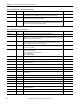
Channel UINT This is the port or channel on the controller that is connected to the drive. For this UDFB, it is
recommended to use a 2080-SERIALISOL module instead of the embedded serial port.
2, 5, 6, 7, 8, and 9
NodeAddr USINT Each drive has a node address that the Modbus Master uses to reference that drive. For each
Modbus network, those addresses must be unique.
1…247
Interval UDINT This parameter is used to control how often the UDFB sends Modbus messages to the device.
Zero representing the Continuous Operation mode. In Continuous mode, the drive status updates
as often as possible given the network traffic and buffer.
0…65,536 ms
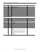
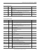
Table 14 - RA_K3_MBUS_STS_Extended Input
Variable Type Description Range
FBENO BOOL This variable reflects the state of the Function Block Enable bit (FBEN). 1, 0
FB_Q BOOL This variable shows whether the status message has completed. After the response from the
drive has been received, this bit becomes true. It stays true until another message is sent or until
UDFB sees a rising edge of the enable input.
1, 0
CommLoss BOOL This bit signifies a communication timeout between the controller and the drive. This also
triggers FB_Error to be true. This is cleared after a successful completion of a message to the
drive or the UDFB sees a rising edge of the enable input.
1, 0
FB_Error BOOL This bit shows that an error occurred within the UDFB. For a more detailed description of the
error code, see FB_ErrCode.
1, 0
FB_ErrCode UDINT This variable enumerates the errors that have occurred within the UDFB. This UDFB has the
following error designations:
Bit 0 - Modbus Message Communication Error.
Bit 1 - Invalid Channel.
Bit 2 - Invalid Node Address.
—
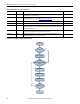
VelocityFdbk INT This value is the motor feedback velocity in revolutions per minute. —
VelocityCmd INT This value is the motor command velocity in revolutions per minute. —
VelocityErr INT This value is the difference between the motor command and motor feedback velocity, in
revolutions per minute.
—
TorqueCmd REAL This value is the commanded current to the motor, in percent of maximum for the drive. —
PosnFdbk DINT This value is the motor feedback position in encoder counts. —
PosnCmd DINT This value is the motor command position in encoder counts. —
PosnErr DINT This value is the difference between the motor command and motor feedback position, in
encoder counts.
—
PlsCmdFreq REAL This is the frequency of pulses, in pulses per second, while in Position Follower mode. —
ElecAngle REAL This is the electrical angle of the motor, in degrees. —
MechAngle REAL This is the mechanical angle of the motor, in degrees. —
ShuntLoad INT This is the regenerative loading, in percent of maximum. —
BusVoltage INT This is the bus voltage, in volts. —
EncTurnCount INT This is the absolute encoder turn count. It is active only when the encoder is using absolute
feedback with a battery.
—
AlarmCode INT This is the most recent alarm code registered by the drive. —
AlarmText STRING This is the alarm message associated with the most recent alarm code. —
Table 13 - RA_K3_MBUS_STS_Extended Inputs (continued)
Variable Type Description Range