
User Manual


52 Rockwell Automation Publication CC-QS033A-EN-P - February 2014
Chapter 2 System Validation
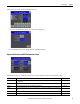
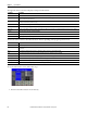
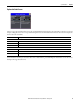
The right side is where you configure and monitor status of the High Speed Counter.
To use the Kinetix 3 and HSC Configuration screen, do the following.
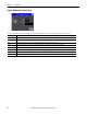
1. Press the Config HSC_K3 button.
The Kinetix 3 drive and HSC configuration screen is displayed.
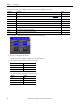
2. Type the following for Kinetix 3 drive configuration.
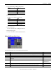
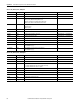
The Kinetix 3 drive status displays the following.
Parameter Description Range
HSC ID This parameter shows the ID of HSC selected. The ID selected also corresponds to the input terminals for the encoder. 0…5
HSC mode This is the HSC mode selected, refer to Micro830 and Micro850 Programmable Controllers, publication 2080-UM002 for
details.
0…9
Initial Pos This is the starting count value during initial startup and upon reset. —
Enable Press this button to start HSC. —
Disable Press this button to stop HSC. —
Reset Press this button to reset count value to Initial Pos. —
HSC Rdy This status indicator shows if a High Speed Counter is properly configured. —
HSC Err This status indicator shows if there is a HSC fault. —
HSC Cnt This status indicator shows the count value of the HSC. —
Attribute Setting
Channel 5
Node 1
Interval 10
Attribute Setting
DrvRdy Rdy
DrvAlarm no fault (if there is no fault)
AlmCode 0 (if there is no fault)