
User Manual

Rockwell Automation Publication CC-QS033A-EN-P - February 2014 51
System Validation Chapter 2
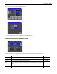
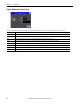
Follow these steps to use the Axis Configuration screen.
1. From Command & Status Screen, press the Axis Config button.
2. Press the Enable buttons for Enable Positive and Enable Negative.
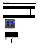
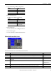
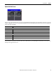
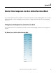
Explore the Kinetix 3 and HSC Configuration Screen
The left side is where you configure communication settings and monitor the status for Kinetix 3 drive.
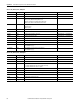
Parameter Description Range
Channel This is the channel on the controller that is connected to the drive. The channel number is for the left-most plug-in slot
starting with five.
5…9
Node Each drive has one node address that the building block uses to reference that drive. This address must be unique. 1…247
Interval This parameter indicates the update rate of Kinetix 3 drive parameters. 0… 65,536 ms
DrvRdy This status indicator shows if a drive is properly configured and connected. It indicates Rdy when there is a valid Kinetix 3
drive.
—
DrvAlarm This status indicator monitors the alarm for Kinetix 3 drive. If there is a fault, the indicator shows Drv Fault. —
AlmCode This status indicator shows the alarm code if the drive is faulted. —