
User Manual

40 Rockwell Automation Publication CC-QS033A-EN-P - February 2014
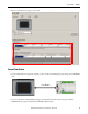
Chapter 2 System Validation
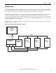
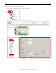
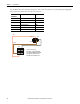
The modified cable can be made by removing one end to expose the conductors. See the following wiring diagram,
but note that the red wire does not need to be connected.
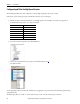
1
B
A
2
3
4
1234
(View in to terminal block)
Pin A1 RS485 + 485Pin B1 RS232 DCD
Pin A2 RS232/485 GNDPin B2 RS232 RXD
Pin A3 RS232 RTS Pin B3 RS232 TXD
Pin A4 RS232 CTS Pin B4 RS485 - 485
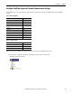
Comm0A or
Comm0B Pin
Description Signal
1 RS-232 transmit XMT
2 RS-232 receive RCV
3Reserved —
4 +5V power ground GND
5 RS-485+ DX+
6 RS-485 DX-
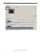
Pin 2
Pin 6
Pin 5
Pin 1
Back
Front
Red
Brown
Black