
User Manual


28 Rockwell Automation Publication CC-QS033A-EN-P - February 2014
Chapter 1 Micro800 Controller PTO Axis Setup
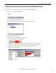
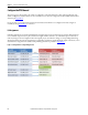
Here's an example of photoelectric type sensor selected and added in the Sensor section of SDA.
Figure 6 - Example Of Photoelectric Sensor Type
Configure Drive Communication
There is no default communication configuration in the starting project file. You must enter the attributes for the drive-
status communication you want to monitor.
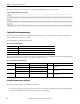
Enter the attributes for the following variables.
Table 1 - Communication Variables
The example in the table below uses the name [Axis_01] for the PTO motion building block, communicating through the
SERIALISOL plug-in module in slot 1, at a refresh rate of 100 ms interval.
Table 2 - Communication Variables Example
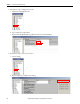
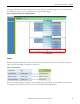
Configure Communication Attributes
Follow these steps to configure the commutation attributes.
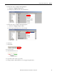
1. From the starting project or the project generated by the CCAT generation function, double-click Global Variables.
2. Scroll to find and select the global variable names that require updating.
Attribute Description
Channel Number This is the location of the SERIALISOL plug-in module on the Micro800 controller plug-in slot.
Node Address This is drive address.
Interval This is the refresh rate of the drive status in milliseconds.
Attribute Global Variable Name Description Initial Value Description
Channel Number Axis_01_Cfg_Channel_Man Channel number in Manual mode control. 5 This indicates that the SERIALISOL plug-in module is
in plug-in slot 1.
Axis_01_Cfg_Channel_Auto Channel number in Auto mode.
Node Address Axis_01_Cfg_NodeAddr_Man Node address in Manual mode control. 1 This indicates that the communicating drive has an
address of 1.
Axis_01_Cfg_ NodeAddr _Auto Node address in Auto mode.
Interval Axis_01_Par_Interval_Man Status refresh in Manual mode control. 100 This indicates that the status refresh for the drive
status is 100 ms.