Quick Start Motion Control PTO Application Building Block Connected Components Accelerator Toolkit
Important User Information Read this document and the documents listed in the additional resources section about installation, configuration, and operation of this equipment before you install, configure, operate, or maintain this product. Users are required to familiarize themselves with installation and wiring instructions in addition to requirements of all applicable codes, laws, and standards.
Where to Start Connected Components Accelerator Toolkit Outline Follow this path to complete your Connected Components Accelerator Toolkit (CCAT) project.
Where to Start Notes: 4 Rockwell Automation Publication CC-QS033A-EN-P - February 2014
Table of Contents Preface About This Publication. . . . . . . . . . . . . . . . . . . . . . . . . . . . . . . . . . . . . . . . . . . . . 7 Terminology. . . . . . . . . . . . . . . . . . . . . . . . . . . . . . . . . . . . . . . . . . . . . . . . . . . . . . . 8 Additional Resources . . . . . . . . . . . . . . . . . . . . . . . . . . . . . . . . . . . . . . . . . . . . . . . 9 Available Connected Components Accelerator Toolkits . . . . . . . . . . . . . .
Table of Contents Explore the Kinetix 3 Status Screen . . . . . . . . . . . . . . . . . . . . . . . . . . . . 56 Explore the Fault Screen. . . . . . . . . . . . . . . . . . . . . . . . . . . . . . . . . . . . . . . 57 Appendix A Kinetix 3 Drive Component-class User-defined Functional Block PTO Application Building Block User-defined Function Block . . . . . . RA_Motion_Move_Cmd User-defined Function Block . . . . . . . . RA_K3_MBUS_STS User-defined Function Block . . . . . . . . . . . . . . . . .
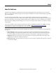
Preface About This Publication This quick start is designed to provide instructions for implementing a Pulse-Train Output (PTO) motion control of a Kinetix® 3 component-class drive by using Connected Components Workbench™ software and a Micro800™ programmable logic controller (PLC). To assist in the design and installation of your system, application files and other information are provided by the Connected Components Accelerator Toolkit (CCAT).
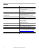
Preface Terminology 8 Term (abbreviation) Definition Application Sequence Programs User-modified programs that work together with the standard state machine logic to control what the machine does while in the abort, clear, reset, run and stop states. Auto/manual Operation When the PanelView™ Component terminal is in Auto mode, the controller logic controls the machine and monitors machine status. When the PanelView Component terminal switches to Manual mode, the terminal takes over control.
Preface Additional Resources These documents contain additional information concerning related products from Rockwell Automation. Resource Description Connected Components Accelerator Toolkit DVD, publication CC-QR002 Provides files for the Connected Component Accelerator Toolkits. Micro800 and Connected Components Workbench Getting Started Guide, publication 2080-QR001 Provides information on basic Micro800 controller and Connected Components Workbench software functions.
Preface Notes: 10 Rockwell Automation Publication CC-QS033A-EN-P - February 2014
Chapter 1 Micro800 Controller PTO Axis Setup In this chapter, you configure a Pulse-Train-Output channel in a Micro800 controller to control a Kinetix 3 drive. You set up the Modbus RTU communication for the controller to monitor drive status. Before You Begin Review the Getting Started CCAT with System Design Assistant Quick Start, publication CC-QS035.
Chapter 1 Micro800 Controller PTO Axis Setup Follow These Steps Follow these steps to configure your Micro800 Controller and Kinetix 3 drive for PTO.
Micro800 Controller PTO Axis Setup Chapter 1 Configure the Kinetix 3 Drive In this section, you configure your personal computer and Series B Kinetix 3 drive with firmware revision 3.005 by using Connected Components Workbench version 6 or later software. You can find the hardware series identifier on the label attached to the side of the product. See Figure 1 and Figure 2 to identify the Series of your Kinetix 3 drive.
Chapter 1 Micro800 Controller PTO Axis Setup Configure Your Kinetix 3 Drive and Personal Computer Connection Follow these steps to configure the connection between your personal computer and your drive. 1. Verify your Kinetix 3 drive is Series B with firmware revision 3.005 or later. Refer to page 13 for examples. 2. Use the keypad on the front of the drive to set the following parameters. Parameter Name Parameter Setting Drive Address Pr0.07 248 Serial Port Configuration Pr0.
Micro800 Controller PTO Axis Setup Chapter 1 6. Expand the Ports (COM & LPT) group, and locate the Allen-Bradley® 1203-USB device. The COM port is specified in parenthesis next to the device name, COM3 in this example. It can be different on your computer. 7. Note your COM port name and close the Device Manager window. 8. To configure an RS-232 DF1 driver, start RSLinx® Classic software. 9. From the Communication menu, choose Configure Drivers.
Chapter 1 Micro800 Controller PTO Axis Setup The Configure Drivers dialog box appears. 10. From the Available Driver Types pull-down menu, choose RS-232 DF1 devices. 11. Click Add New. The Add New RSLinx Classic Driver dialog box appears. 12. Type a name for your driver, You can use the default name, if desired. 13. Click OK.
Micro800 Controller PTO Axis Setup Chapter 1 14. Configure the driver settings. a. From the Comm Port pull-down menu, choose the port number of your 1203-USB serial adapter. b. From the Device pull-down menu, choose PLC-CH0. c. From the Baud Rate pull-down menu, choose 115200 baud rate. d. From the Error Checking pull-down menu, choose CRC. IMPORTANT Do not click auto-configure. b a c d 15. Click OK. 16.
Chapter 1 Micro800 Controller PTO Axis Setup 17. Expand your RS-232 DF1 driver, and verify that your drive is displayed. It is listed as 01, AB DSI. If the drive is not displayed below the driver, check your COM port and driver settings. 18. Close RSLinx Classic software. Connect to Your Drive Follow these steps to connect to the Kinetix 3 drive. The Kinetix 3 drive must be Series B or later with firmware revision 3.005 or later. 1.
Micro800 Controller PTO Axis Setup Chapter 1 2. From the Connection Browser, under AB_DF1-1, select your drive (01, AB DSI) and click OK. A drive is added to the Project Organizer and the drive's Device Details window appears in the main project workspace. TIP First time uploads take longer. 3. Follow these step to reset the drive to default settings. This provides consistent drive settings. a. From the Toolbar, click the Wizard icon.
Chapter 1 Micro800 Controller PTO Axis Setup b. Select Kinetic 3 Startup Wizard and click Select. c. Click Reset to Factory Settings. The drive is resets. d. Click Finish.
Micro800 Controller PTO Axis Setup Chapter 1 Configure Your Drive by Using Connected Components Workbench Software Follow these steps to configure your drive parameters for the PTO building block. 1. From the Tool bar, click the Wizard icon. The Available Wizards dialog box appears. 2. From the list, select the Kinetix 3 Configuration wizard and click Select. The application window appears. 3. Follow these steps to configure the Follower mode. a. Click Next until Follower is highlighted. b. c. d. e.
Chapter 1 Micro800 Controller PTO Axis Setup 4. Follow these steps to configure the encoder. a. Click Next to highlight Encoder. b. Type 1:128 for the Output Ratio. c. From the Encoder Backup Battery pull-down menu, choose Not Installed. b c 5. Follow these steps to auto tune your motor. a. Choose Tuning. b. From the right pane, click Start Autotuning.
Micro800 Controller PTO Axis Setup Chapter 1 6. Follow these steps to configure the Digital Inputs. a. Click Next to highlight Digital Inputs. b. From Input 2 pull-down menu, choose Fault Reset. 7. Follow these steps to configure the Digital Outputs. a. Click Next to highlight Digital Outputs. b. From Output 1 pull-down menu, choose Ready. 8. Click Next. 9. Click Finish. 10. Save the project. 11. Click the Disconnect icon. 12. Upload the online values to project file. 13.
Chapter 1 Micro800 Controller PTO Axis Setup Configure the Micro800 Controller In this section you generate or get a Connected Components Workbench project with servo drive for a PTO application. You do this by using the CCAT generation function or download the starting project Starting_PTO_r6 from sample code. To get a starting project go to the website: http://search.rockwellautomation.com/ search?site=sample_code&client=samplecode&output=xml_no_dtd&proxystylesheet=samplecode.
Micro800 Controller PTO Axis Setup Chapter 1 2. From the Controller Change dialog box, type and use the pull-down menu to set the following attributes. Attribute Setting Project Name PTO_M850_24QBB_r5 Controller Name Micro850 Controller type 2080-LC50-24QBB 3. Click OK. A new project named, PTO_M850_24QBB_r5, is created in your My Document > CCW folder and the output dialog box reports that the controller change is successful.
Chapter 1 Micro800 Controller PTO Axis Setup Configure the PTO Channel The starting project from sample code website is configured to work with the Kinetix 3 drive and wiring diagram. The default configuration includes a PTO axis. You can find out more about the configuration in Micro800 Controller PTO Axis Setup in Appendix C. For project that is generated with the CCAT generation function the PTO is not configured. You must configure it manually by using Appendix C as a reference.
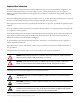
Micro800 Controller PTO Axis Setup Chapter 1 The output terminal for Drive Reset Output must be properly assigned in each ladder program. The output terminal is on the third branch of rung one each _Motion ladder diagram. Figure 4 - Output Terminal for Drive Reset Output Assignment Sensors In the I/O assignment diagram above, there is a section for sensor connections. The sensors are connected to dedicated input terminals corresponding to the PTO channel selected.
Chapter 1 Micro800 Controller PTO Axis Setup Here's an example of photoelectric type sensor selected and added in the Sensor section of SDA. Figure 6 - Example Of Photoelectric Sensor Type Configure Drive Communication There is no default communication configuration in the starting project file. You must enter the attributes for the drivestatus communication you want to monitor. Enter the attributes for the following variables.
Micro800 Controller PTO Axis Setup Chapter 1 3. Type value under the Initial Value column for each variable. 4. Repeat starting at step 1 until you have updated all six variables required for monitoring the drive status. 5. Build and download your project.
Chapter 1 Micro800 Controller PTO Axis Setup Notes: 30 Rockwell Automation Publication CC-QS033A-EN-P - February 2014
Chapter 2 System Validation In this chapter, you confirm the following: • Communication between controller and PanelView Component terminal • Controller generates the appropriate pulse output to control the motor • Communication between controller and Kinetix 3 servo drive The operation of the sample code and screens is also explained. Before You Begin • Review all steps in Chapter 1. • Verify that all of the devices are connected as shown in the wiring diagram.
Chapter 2 System Validation Follow These Steps Complete these steps to configure, connect your devices, down load program to the controller, transfer HMI application to PanelView component terminal, and validate your system.
System Validation Chapter 2 System Overview The PTO Building Block is a device building block that consists of screen designs for PanelView Component terminal and logic code for Micro800 controller to send pulse-train-output commands to control servo or stepper drives. Utilizing the screen design and code, you can perform move commands, homing, and troubleshoot motion faults. The PanelView Component terminal is connected to the embedded serial port of Micro800 controller.
Chapter 2 System Validation Configure Your Controller Serial Port The Micro800 controller communicates with PanelView Component terminal and Kinetix 3 drive through the embedded serial port and 2080-SERIALISOL plug-in. The embedded serial port is called channel 2 and the first plug-in slot is called channel 5. The following settings are used for each port.
System Validation Chapter 2 Follow these steps to modify the serial port settings. 1. From the Project Organizer, double-click the Controller icon. 2. From the Controller tree select the serial port and edit the settings.
Chapter 2 System Validation Configure Input Filter for High Speed Counter The default input filter value can be adjusted to count the high-speed pulses from your encoder. Follow these steps to change the input terminal filter value for your encoder input. 1. Identify the input terminal with reference to the High Speed Counter (HSC) selected for your application. Each HSC ID corresponds to a set of input terminals.
System Validation Chapter 2 Configure PanelView Component Terminal Communication Settings In the default project, the communication and controller settings have already been configured. Here are the default settings.
Chapter 2 System Validation 2. Click the Communication icon.
System Validation Chapter 2 3. Edit the communication settings to your needs. Connect Your Devices 1. Connect the PanelView Component terminal to your controller's embedded serial port by using a 1761-CBL-PM02 cable. 1761-CBL-PM02 2. Connect your Kinetix 3 drive's IEEE1394 plug to your Micro800 controller's isolated serial port (2080SERIALISOL) by using a modified 2090-CCMDSDS-48AA01 cable.
Chapter 2 System Validation The modified cable can be made by removing one end to expose the conductors. See the following wiring diagram, but note that the red wire does not need to be connected.
System Validation Chapter 2 Download Your Program to the Controller Follow these steps to download your program to your controller. 1. Connect an available USB port on your personal computer to the USB programming port on your Micro800 controller by using a USB A-to-B cable. 2. Build your program. If you are prompted to install drivers, specify to use the recommended drivers. 3. From your Connected Components Workbench project, right-click on your device icon. 4. From the Project Organizer, choose Build.
Chapter 2 System Validation 6. From the Project Organizer, right-click on your device icon and choose Download. 7. From the Connection Browser dialog box, select your controller and click OK. 8. If prompted to change the Controller mode to Remote Program, click Yes. The program downloads and you are prompted to change the Controller mode to Remote Run. 9. Click Yes.
System Validation Chapter 2 Configure the IP Address for Your PanelView Component Terminal Follow these steps to configure a static IP address on the PanelView Component terminal. 1. From the Main menu, press Communication to open the Communication screen. 2. Press Set Static IP Address. 3. Configure the IP Address and Mask values so they are in the same range as your Micro800 controller. 4. Press Main to return to the Main menu.
Chapter 2 System Validation 4. In the Project Organizer, right-click the PanelView Component terminal icon and choose Download. 5. In the Graphic Terminal Application Download dialog box, enter the IP address of your PanelView Component terminal that you configured in the section above. 6. Click Download. 7. Verify that the download completed successfully. 8. From the Main menu of your PanelView Component terminal, press File Manager. 9. On the File Manager screen, select Internal as your Source. 10.
System Validation Chapter 2 11. Press Run.
Chapter 2 System Validation Validate Your System In this section, you review the Machine Overview and Machine Functions screens and explore the Status and Command screens to test the manual control of the building block. Understand the Machine Overview Screen The Machine Overview screen in the default project is common to all CCATs. When this screen is first loaded, you can complete the following tasks: a. Return to the Configuration screen and exit the program. b. View and change current machine state.
System Validation Chapter 2 From Axis_01 screen in Auto mode, you can monitor the following status: • Axis command velocity • Axis command position • High Speed Counter (HSC) count • Axis status • Servo drive status Here you test the manual control of the Building Block. There are two manual modes for selection, Basic and Advance modes. Press Manual and Axis_01 buttons to enter the first manual screen.
Chapter 2 System Validation Explore the Command and Status Screen The left side shows the servo status indicator is describe here. Parameter Description Axis Enabled This status indicator displays whether the axis is active and the drive is maintaining control of the motor. Homed This status indicator displays the home status of the drive. If the status indicator is green, the drive has an absolute position reference. When the box is gray, the drive is not homed.
System Validation Chapter 2 The bottom of the screen has control buttons that inactivate depending on the program operation mode. Parameter Description Servo Enable/ Disable This maintain-push button enables and disables the servo drive. Start Homing This momentary-push button starts the homing process for the drive. It is available only when the drive is stopped, enabled, and while the program is in Manual mode.
Chapter 2 System Validation The motor begins to home according to the selected homing method shown here. Homing Mode Homing Mode Name Value Homing Mode Description 0x00 MC_HOME_ABS_SWITCH Homing process searches for Home Absolute switch. 0x01 MC_HOME_LIMIT_SWITCH Homing process searches for limit switch. 0x02 MC_HOME_REF_WITH_ABS Homing process searches for the Home Absolute switch and the encoder reference pulse.
System Validation Chapter 2 Follow these steps to use the Axis Configuration screen. 1. From Command & Status Screen, press the Axis Config button. 2. Press the Enable buttons for Enable Positive and Enable Negative. Explore the Kinetix 3 and HSC Configuration Screen The left side is where you configure communication settings and monitor the status for Kinetix 3 drive. Parameter Description Range Channel This is the channel on the controller that is connected to the drive.
Chapter 2 System Validation The right side is where you configure and monitor status of the High Speed Counter. Parameter Description Range HSC ID This parameter shows the ID of HSC selected. The ID selected also corresponds to the input terminals for the encoder. 0…5 HSC mode This is the HSC mode selected, refer to Micro830 and Micro850 Programmable Controllers, publication 2080-UM002 for details. 0…9 Initial Pos This is the starting count value during initial startup and upon reset.
System Validation Chapter 2 3. Type the following for HSC configuration. Attribute Setting HSC ID 2 HSC mode 6 Initial Pos 0 4. Press the Enable button. The HSC status displays the following. Attribute Setting HSC Rdy HSC On HSC Err No Fault HSC Cnt 0 (the value changes as you rotate your encoder) 5. Press the X button. You are returned to Axis Configuration Screen. 6. Press X button again. 7. You are returned to Command & Status Screen.
Chapter 2 System Validation The right side shows some numeric displays and inputs described below. Parameter Description Axis Enabled The status indicator shows whether the axis is active and the drive is maintaining control of the motor. Homed This status indicator shows the home status of the drive. When the status indicator is gray, the drive is not homed. When the status indicator is green, the drive has an absolute position reference.
System Validation Chapter 2 2. Enter value for the following motion parameter for velocity control. Parameter Value Description Deceleration 100 100 mm/s2 Acceleration 100 100 mm/s2 Direction 1 Forward Velocity 100 100 mm/s 3. Press the Servo Enable button. This energizes the motor, and it attempts to hold its present position. 4. Press the Move button. The motor turns, accelerates, and cruises at 100 mm/s. 5. Press the Halt button. Motor decelerates to a stop. 6.
Chapter 2 System Validation Explore the Kinetix 3 Status Screen This screen indicates the status of any configured Kinetix 3 drive. It does not work with any other servo drive. Parameter Description Node This parameter shows the node address of connected drive. Comm When this status indicator is gray, communication is active. When this status indicator is red communication has breaks. Alarm When this status indicator is grey, there are no alarms. When the status indicator is red there is an alarm.
System Validation Chapter 2 Explore the Fault Screen There are two separate faults in this screen. The Command Fault is fault related to the command you issued to an axis. For example, asking the axis to move or stop with invalid parameter. The Axis Fault is fault related to the axis. For example, the axis has detected a hard limit. Parameter Description Command Fault Error code This shows the error code for motion instruction. Error ID This shows a short name for the error.
Chapter 2 System Validation Notes: 58 Rockwell Automation Publication CC-QS033A-EN-P - February 2014
Appendix A Kinetix 3 Drive Component-class User-defined Functional Block Six user-defined function blocks (UDFBs) are included with the Kinetix 3 Drive Building Block. All are used in the device module code for returning the status of the drive, sending commands to the drive, and configuring parameters. PTO Application Building Block User-defined Function Block This appendix describes the user-defined function blocks used in the PTO building block and the associated inputs and outputs.
Appendix A Kinetix 3 Drive Component-class User-defined Functional Block Table 7 - RA_Motion_Move_Cmd Inputs Variable Data type Description Range FBEN BOOL Set this bit TRUE to enable the function block. 0, 1 AxisIn Axis_Ref Assign this to the motion axis created via the configurator. — MoveMode INT 0: Maintenance mode, Jogging is permitted. 1: Velocity control, Motion is in Velocity Move mode. 2: Absolute control, Motion is in Absolute Position Move mode.
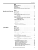
Kinetix 3 Drive Component-class User-defined Functional Block Appendix A Figure 8 - RA_Motion_Move_Cmd Function Block Flowchart Start Servo Off Yes Axis Error? Clear Fault Servo On No Select Move Mode Yes Error? No Read Motion Parameters Correct Parameter No Execute Halt? Yes Yes Yes Correct Parameter Execute Move? Motion Error? Motion Error? No Yes No Await Action Completed Stop PTO Start PTO End Rockwell Automation Publication CC-QS033A-EN-P - February 2014 61
Appendix A Kinetix 3 Drive Component-class User-defined Functional Block Table 9 - RA_HSC_CfgAndSts Inputs Variable Data type Description Range FBEN BOOL Set this bit TRUE to enable the function block. 0, 1 HscID UINT This value sets the ID in use. 0…5 HscMode USINT This value sets the HSC mode. 0…9 Enable BOOL Set this bit TRUE to enable the HSC. 0, 1 Disable BOOL Set this bit TRUE to disable the HSC. 0, 1 InitialPosition REAL This value sets the initial position after reset.
Kinetix 3 Drive Component-class User-defined Functional Block Appendix A Figure 9 - RA_HSC_CFGandSTS Function Block Flowchart Start Initialize HSC Read HSC Parameter No Rest HSC? Yes Rest Initial Count Value Enable HSC ? No Yes Invalid Parameter? Reset HSC Yes No HSC Counting Disable HSC No Yes End Rockwell Automation Publication CC-QS033A-EN-P - February 2014 63
Appendix A Kinetix 3 Drive Component-class User-defined Functional Block RA_K3_MBUS_STS User-defined Function Block This UDFB provides the basic status word for the Kinetix 3 drive. The outputs are updated at the interval specified on the input side of the function block.
Kinetix 3 Drive Component-class User-defined Functional Block Appendix A Table 11 - RA_K3_MBUS_STS Inputs Variable Type Description Range FBEN BOOL The Function Block Enable bit (FBEN) controls the operation of the function. On the rising edge of 1, 0 this bit, the function block initialization takes place. While this bit is held high, the function block continues to execute. Channel UINT This is the port or channel on the controller that is connected to the drive.
Appendix A Kinetix 3 Drive Component-class User-defined Functional Block Table 12 - RA_K3_MBUS_STS Outputs (continued) Variable Type Description Range NearPosn BOOL This bit is true when the motor feedback position is within the position tolerance specified by parameter Pr5.02 - Near Position Size. 1, 0 Warning BOOL This bit is true when there is a warning on the drive. Warning descriptions can be seen in the Kinetix 3 drive’s user manual. See the Additional Resources on page 9.
Kinetix 3 Drive Component-class User-defined Functional Block Appendix A RA_K3_MBUS_STS_Extended User-defined Function Block This UDFB retrieves the extended status information from the drive. The drive supports only two analog outputs; this lets many more values be updated. The output values are updated at the interval specified by the input interval.
Appendix A Kinetix 3 Drive Component-class User-defined Functional Block Table 13 - RA_K3_MBUS_STS_Extended Inputs (continued) Variable Type Description Range Channel UINT This is the port or channel on the controller that is connected to the drive. For this UDFB, it is recommended to use a 2080-SERIALISOL module instead of the embedded serial port. 2, 5, 6, 7, 8, and 9 NodeAddr USINT Each drive has a node address that the Modbus Master uses to reference that drive.
Kinetix 3 Drive Component-class User-defined Functional Block Appendix A Figure 11 - RA_K3_MBUS_STS_Extended Function Block Flowchart Start First Scan? No Yes Initialize Variables Are Channel and Node Address Within Range? Yes Set Error Bits Read Drive Status Run Diagnostics No End Diagnostics? Yes End Rockwell Automation Publication CC-QS033A-EN-P - February 2014 69
Appendix A Kinetix 3 Drive Component-class User-defined Functional Block Notes: 70 Rockwell Automation Publication CC-QS033A-EN-P - February 2014
Appendix B Global Variables This appendix contains the global variables used for the user program interfacing. Table 15 - Global Variable Variable Name Data Type Variable Description (User-defined prefix)_Cfg_MoveMode_Auto INT 0: Maintenance mode (lets only the axis jog) 1: Velocity Move mode 2: Absolute Move mode 3: Relative Move mode (User-defined prefix)_Cfg_EnNegative_Auto BOOL Enable motion in the negative direction.
Appendix B Global Variables Table 15 - Global Variable (continued) Variable Name Data Type Variable Description (User-defined prefix)_Cmd_HscRset_Auto Execute to reset High Speed Counter BOOL Applicable only when using an encoder. (User-defined prefix)_Cfg_HscMode_Auto Selection of High Speed Count mode UINT Applicable only when using an encoder. (User-defined prefix)_Cfg_HscID_Auto Selection of High Speed Counter UINT Applicable only when using an encoder.
Appendix C Motion Axis Setup for PTO Building Block I/O Assignment The I/O assignments differ for the number of PTO applications used. The following figures are shown for your reference. You can change the assignment as needed for your application.
Appendix C Motion Axis Setup for PTO Building Block Figure 13 - I/O Assignment for a Drive with Two PTO Applications 74 Rockwell Automation Publication CC-QS033A-EN-P - February 2014
Motion Axis Setup for PTO Building Block Appendix C Figure 14 - I/O Assignment for a Drive with Three PTO Applications Rockwell Automation Publication CC-QS033A-EN-P - February 2014 75
Appendix C Motion Axis Setup for PTO Building Block The output terminal for each Drive Reset Output is assigned in each ladder program. The assignment is on the third branch of rung 1 for each of the PTO building block ladder diagrams Figure 15 - Sample of a PTO Building Block Ladder Diagram General 1. Type your axis name in the Axis Name field. A system variable is created for the name entered in the Axis Name field.
Motion Axis Setup for PTO Building Block Appendix C If your project was generated by CCAT System Design Assistant, use the name given when you set up the PTO application. By default, the first PTO application is call ServoDrive1 and subsequent applications are called ServoDrive2 and ServoDrive3. The names of axes for PTO applications created with Connect Components Workbench motion configuration are shown here. 2. Select your preferred PTO channel.
Appendix C Motion Axis Setup for PTO Building Block 3. Verify Drive Enable Output is enabled. In the configuration shown, the motion command, MC_Power, activates the output when executed successfully. a. Check Drive Enable Output. When this box checked the MC_Power initiates motor enable. b. From the Output pull-down menu, choose the output terminal to initiate motor enable. c. From the Active Level pull-down menu, choose the Output signal active level.
Motion Axis Setup for PTO Building Block Appendix C 5. Verify Drive Ready Input has been enabled. In the configuration shown, the controller requires an external signal to indicate that the drive is ready. It is usually used to show if a drive is faulted. The drive sends a TRUE to this input if it is ready. a. Check Drive Ready. When checked, Drive Ready Input is enabled. b. From the Input pull-down menu, choose the input terminal you want to use for Drive Ready signal. c.
Appendix C Motion Axis Setup for PTO Building Block Motor and Load 1. Verify the SI unit for position has been set to mm. This unit is used in the rest of the configuration for position and speed. This setting does not have any effect on the configuration. 2. Verify the ratio of 10:1,024 has been set. This ratio generates the number of pulses to reach the required position value. a. Type value for Pulse per Revolution. This value syncs up with the drive settings.
Motion Axis Setup for PTO Building Block Appendix C 3. Verify the direction configuration for the PTO channel. a. From the Polarity pull-down menu, choose the setting appropriate for your application. This setting lets you to invert the directional signal. b. From the Mode pull-down menu, choose the Mode appropriate for your application. The Bi-Directional setting to let the motion axis to move in the positive and negative direction. c.
Appendix C Motion Axis Setup for PTO Building Block 2. Verify the soft limit configuration. In the configuration shown the soft limits are not used, if your application uses soft limits do the following. a. Check Lower Soft Limit and Upper Soft Limit. When the boxes are checked, the soft limit are enabled. b. Type the values for the soft limit position. The SI unit is in mm, as defined in Motor Load section.
Motion Axis Setup for PTO Building Block Appendix C Dynamics 1. Verify the maximum motion profile level for your application. a. Type the value for maximum speed for your application. The maximum speed for a Kinetix 3 drive is 5000 rpm. b. Type the value for Start/Stop Velocity. The Start and Stop velocity is define as 50% of the max velocity. c. Verify the values for acceleration, deceleration and jerk. In this example the maximum value has been set for acceleration, deceleration and jerk.
Appendix C Motion Axis Setup for PTO Building Block 2. Define the motion type and dynamics for Emergency Stop Profile. a. From the Stop Type pull-down menu, choose an Emergency Stop Profile for your application. In this example Deceleration Stop is defined as the Emergency Stop Profile. b. Type the value for Stop Velocity In this example the Stop Velocity has been set to 50.0 rpm. c. Type values for Stop Deceleration and Stop Jerk.
Motion Axis Setup for PTO Building Block Appendix C Homing 1. Define the parameters for the homing sequence. a. From the Homing Direction pull-down menu, choose a home direction for your application. In this configuration the Home direction is set to negative. The axis moves in the negative direction when motion home command is executed. b. Type a the value for Homing Velocity. In this configuration the axis moves at 5.0 mm/s when MC_Home is executed. c.
Appendix C Motion Axis Setup for PTO Building Block Notes: 86 Rockwell Automation Publication CC-QS033A-EN-P - February 2014
Appendix D Configure a Series A Kinetix 3 Drive This appendix provides the steps for configuring Kinetix 3 drive Series A hardware with Ultraware software. What You Need Kinetix 3 drive setup: • Personal computer with an available RS232 port If RS232 port is not available, you can use an available USB port and USB/RS232 converter. • Ultraware Software version 1.82.
Appendix D Configure a Series A Kinetix 3 Drive 6. Connect the drive to your personal computer with the RS-232 serial communication cable. If RS232 port is not available, you can do this with an available USB port and USB/RS232 converter. 2 3 1 Item Description 1 Kinetix 3 drive 2 RS-232 serial communication cable, catalog number 2090-CCMPCDS-23AA 3 Personal computer with Ultraware software Follow these steps to connect the Kinetix 3 drive to your personal computer and the Ultraware software. 1.
Configure a Series A Kinetix 3 Drive Appendix D 5. Navigate to your personal computer’s Device Manager or use the Run command and enter ‘devmgmt.msc’. 6. Determine the COM port you want to use with Ultraware software. This example shows a serial-to-USB converter on Port 3. 7. From the Tools menu in Ultraware software, choose Serial Port.
Appendix D Configure a Series A Kinetix 3 Drive 8. In the personal computer Communication Setup dialog box, configure the serial port, as follows: – Serial Port chosen in step 6 – Baud Rate: 57600 – Format: 8 Data Bits, No Parity 9. Click OK. 10. From the Tools menu, choose Rescan. The drive attaches at Node 1 and appears in the On-Line Drives tree when the scan is complete. 90 If Then Communication was established. You are prompted to use a wizard to set up the Kinetix 3 drive.
Configure a Series A Kinetix 3 Drive Appendix D Configure Your Drive with Ultraware Software Follow these steps to configure your Kinetix 3 drive for the building block. 1. Factory reset the drive to provide a consistent starting point. a. From the top-level branch, double-click Drive. b. From the right pane, click Reset to Factory Settings. c. Click Yes. 2. Configure the Follower mode. a. Expand Mode Configuration. b. Double-click Follower branch. The parameters are shown in the right pane. c.
Appendix D Configure a Series A Kinetix 3 Drive 3. Configure the Encoders settings. a. Double-click the Encoders branch. The parameters are shown in the right pane. b. Set Output Ratio to 1:128. c. Set the Encoder Backup Battery to Not Installed. d. Click Yes. 4. Auto tune the servo motor. a. Double-click the Tuning branch. The parameters are shown in the right pane. b. Click Start Autotuning. c. Check that the motor is safe to operate. d. Click Yes. The motor enables and moves a few steps.
Configure a Series A Kinetix 3 Drive Appendix D 5. Configure Digital Input. a. Double-click the Digital Inputs branch. b. Set Input 2 to Fault reset. 6. Configure Digital Output. a. Double-click the Digital Output branch. b. Set Output 1 to Ready. Configure Your Drive for Modbus Communication Protocol After you configure your Kinetix 3 drive with Ultraware software, follow these steps to set the drive to Modbus mode. 1. Disconnect the serial cable from the personal computer and the drive. 2.
Rockwell Automation Support Rockwell Automation provides technical information on the Web to assist you in using its products. At http://www.rockwellautomation.com/support you can find technical and application notes, sample code, and links to software service packs. You can also visit our Support Center at https://rockwellautomation.custhelp.com/ for software updates, support chats and forums, technical information, FAQs, and to sign up for product notification updates.