
Software Owner manual

Rockwell Automation Publication MOTION-UM004B-EN-P - October 2012 95
Sizing Your System Chapter 2
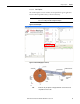
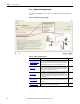
Results
(label 4 in Figure 75
)
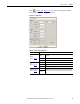
Peak Inertia The calculated maximum reflected inertia at the crankshaft.
Peak Ext. + Grav. Torque
The Peak External Force + Gravity Torque is the calculated peak torque, generated from the external linear force and
gravity.
Apply Click to apply the load profile data and close the window.
Cancel Click to close the window without applying any data.
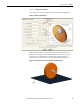
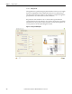
Chart Display
(label 5 in Figure 75
)
The Chart Display displays the crank velocity, the inertia that is reflected to the crankshaft, and the crank torque due to external influences such as gravity
and applied force. These are the parameters which will be applied.
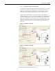
(1) Use the Inertia Calculator Template on page 105 to calculate the inertia value for your application, if the value is not readily available.
(2) Setting this length to zero configures the mechanism as a Scotch Yoke, where the linear load follows a simple harmonic motion.
(3) If the Force at Start is different from the Force at End, the force varies between these two limits according to gudgeon pin position or crank angle. If the values are equal, a constant force is applied.
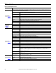
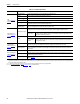
Table 55 - Crank Template Parameters (continued)
Parameter Description