
Software Owner manual

88 Rockwell Automation Publication MOTION-UM004B-EN-P - October 2012
Chapter 2 Sizing Your System
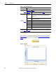
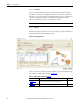
Table 52 - Complex Load Data Options
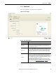
It is important to start with the mechanism in the appropriate position. Click
Start Condition
on the toolbar at the top of the More Options Profile Editor
Mode dialog box to input the motion profile start condition.
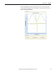
Figure 70 - Graph Tab
Option Description
Complex Load Data
(label 1 in Figure 69
)
User Defined
Import load data from an external file into the Complex Load Data table on
page 90.
Templates
Use the Unbalanced Load and Crank templates to calculate load data and
enter it in the Complex Load Data table on page 90.
Motion
(1)
(label 2 in Figure 69)
(1) The complex load data (position, inertia, and torque, for example) is entered manually, imported, or calculated in the available
Rotary Complex Templates.
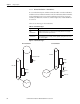
Repeating
With this option, the first and last points should be identical so that the
motion profile can be repeated (for example, zero and 360 °). Motion
Analyzer software assumes that rotation may continue indefinitely in
either direction.
Limited Range
With this option, the first and last points indicate the maximum and
minimum positions permitted.
# Data point number; this number is arbitrary.
Position Driving shaft angle with reference to the starting angle.
Inertia Load inertia for the given shaft angle.
Applied Torque Torque applied at the given position.
Friction Torque Torque loss due to friction.
Description Available for you to enter optional notes.
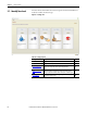
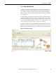
Graph tab
(label 3 in Figure 69
)
The Graph tab of the display window shows the inertia, applied torque, and friction torque
values as a function of shaft position based on the data entered in the table on the left (label 2
in Figure 69).