
Software Owner manual

Rockwell Automation Publication MOTION-UM004B-EN-P - October 2012 57
Welcome to Motion Analyzer Software Chapter 1
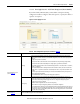
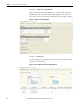
Table 36 - Power Supply/Accessories (refer to Figure 43)
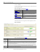
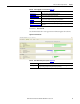
1.2.2.4.4.2.1. Power Data Tab
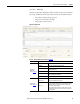
Use the Power Data tab to view regeneration and motoring data for each axis.
Figure 44 - Power Data Tab
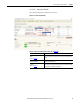
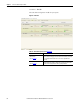
Table 37 - Power Data Tab Properties (refer to Figure 44
)
Parameters Description
Power Data Tab View regeneration and motoring data for each axis.
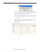
Converter and Shunt Tab
Select the shunt and capacitor for your system.
Analysis Tab
Analyze the drive module activity in terms of bus voltage and system current. With this
tab, you can also simulate changes to the system parameters.
Energy Tab View input current values and energy savings estimates for each axis.
Configure Power Supply BOM
Tab
Configure the bill of materials (BOM) for the power supply after fully sizing the
application.
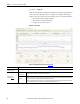
Parameters Description
Axis histograms
The axis histograms show a multi-axis representation of axis currents including peak motoring,
average motoring, peak regenerating, and average regenerating.