
Software Owner manual

Rockwell Automation Publication MOTION-UM004B-EN-P - October 2012 47
Welcome to Motion Analyzer Software Chapter 1
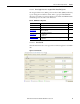
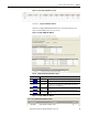
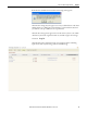
1.2.2.4.3.1. Power Data Tab
Use the Power Data tab to view regeneration and motoring data for each axis.
Table 28 - Power Data Tab Properties (refer to Figure 34)
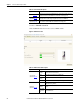
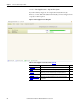
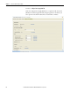
1.2.2.4.3.2. Shunt Tab
Click Search to automatically configure the shunt module catalog number for
each axis.
Figure 35 - Shunt Tab
Table 29 - Shunt Tab Properties
Parameters Description
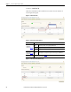
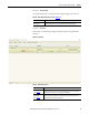
Axis Histograms
The axis histograms show a multi-axis representation of axis currents including Peak
Motoring, Average Motoring, Peak Regenerating, and Average Regenerating.
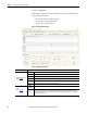
Parameters Description
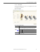
Shunt selection
(refer to Figure 23
)
Click Search to configure external shunts if an existing internal shunt for a given drive is
outside its rating. If you need more than one external shunt, click search to select multiple
shunt modules. You can also select a compatible shunt manually.
Continuous Current
utilization bar
(refer to Figure 23)
The drive continuous and peak current utilizations and the shunt continuous current
utilization histograms are displayed in percentage form. Click the drive module or shunt
catalog number to view its product specification.