
Software Owner manual

Rockwell Automation Publication MOTION-UM004B-EN-P - October 2012 259
Understanding Your System Solution Chapter 3
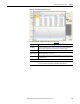
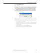
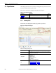
Table 152 - Configure Axis BOM
Parameters Description
Step 1 Motor/Actuator
(refer to Figure 204
)
Select the options required. Options that are not available are dimmed. Standard
options are shown by default.
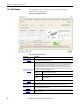
Encoder Options
From the Encoder Options pull-down menu, choose the encoder
type for your motor.
Brake and Key
The brake is chosen during sizing on the Motor tab. The shaft key
will be selected if it is available.
Mounting
Flange
Some motors have different mounting options.
Miscellaneous
Options
Different motors and actuators have various options that can be
selected. Some options such as blowers and covers, for example,
affect sizing and have been selected in the sizing process.
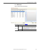
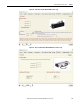
Step 2
Accessories
Select motor and actuator accessories. The rod guide for electric cylinders was
selected during sizing.
Step 3
Axis Module/Drive/IAM
Check for connector kit.
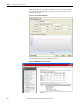
Step 4
Motor/actuator power cable
Check non-flex or continuous-flex cable and cable length options. The length
selected for the power cable is used for the other cables, unless the lengths are
individually changed.
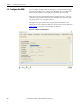
Step 5
Motor/actuator feedback cable
Check non-flex or continuous-flex cable, cable length, and flying-lead or connector
at drive-end options.
Step 6
Motor/actuator brake cable
Check non-flex or continuous-flex cable and cable length options. For most motors,
separate brake cable is not required because brake wires are included in the power
cable.
Step 7
Resistive brake module
Resistive Brake Module for the application is selected in the Axis Stop
tab on page
250 and cannot be changed here.
Step 8
Resistive brake module cables
Specify cable AWG size and cable length options.