
Software Owner manual

Rockwell Automation Publication MOTION-UM004B-EN-P - October 2012 25
Welcome to Motion Analyzer Software Chapter 1
1.2.2.2.2. Axis Summary Image
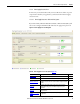
The axis summary images apply to all drive families. In this example, the current
configuration of Kinetix 6000 servo drives includes the drive/motor
combination featured below.
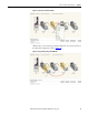
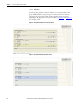
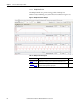
Figure 16 - Axis Summary Bar (servo drive)
Table 11 - Axis Summary Example
In this example, the current configuration includes a Kinetix 6000M power
interface module (IPIM).
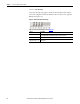
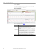
Figure 17 - Kinetix 6000M Power Interface Module
IPIM module icon along with the catalog number of the selected IPIM module is
displayed in this bar. Click + to access the IPIM child nodes (IDM units).
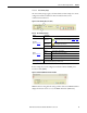
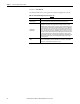
Option Description
Title Band
(label 1 in Figure 16
)
Axis Solution
Status Icon
Axis Solution Status icon indicates the status of the selected
solution. Axis solution status is defined in Solution
on page
208.
Warning Icon
A warning triangle icon indicates a warning with this axis,
which requires your attention.
Axis Name Name of the Axis.
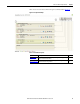
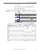
Axis Bar
(label 2 in Figure 16
)
Displays information about the selected drive/motor axis or IPIM module.
Motor
(1)
(1) Configure Motor BOM is available for the selected motor. Click to launch the Configure Motor dialog box.
Selected motor catalog number.
Drive Selected drive module catalog number.
Gearbox Selected gearbox catalog number.
RBM Selected RBM module catalog number.
Short-cuts to Axis view
(label 3 in Figure 16
)
Icons are a graphical representation of the selected axis components. Click icons to switch
to the corresponding data page in the Axis view.