
Software Owner manual

Rockwell Automation Publication MOTION-UM004B-EN-P - October 2012 241
Understanding Your System Solution Chapter 3
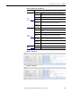
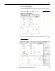
Table 140 - Simulation Plots Tab Definitions
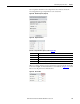
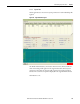
Figure 178 - Position Plots
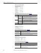
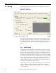
Figure 179 - Velocity Plots
Options Description
Position
(label 1 in Figure 177
)
Motor Position (Default ON) Position of the motor, measured by the feedback device.
Target Position
(Default ON) Position target from motion planner in the controller to the
drive.
Load Position Simulated position of the load.
Position (Δ):
Target-Motor
(Default ON) Difference between Command Position and Actual Position
(when simulation Position Feedback is the same as Actual Position).
Position (Δ):
Target- Load
Difference between Command Position and Load Position.
Position (Δ):
Motor-Load
Difference between Actual Position and Load Position.
Velocity
(label 2 in Figure 177
)
Motor Velocity (Default ON) Velocity of the motor.
Target Velocity
Velocity command in the drive (output of position loop plus velocity feed
forward).
Load Velocity Simulated velocity of the load.
Velocity
Reference
Velocity command in the drive (magnitude & rate limited)
Velocity (Δ):
Target-Motor
Difference between Command Velocity and Velocity Feedback (velocity
feedback is a filtered derivative approximate of position feedback).
Velocity (Δ):
Target- Load
(Default ON) Difference between Command Velocity and Load Velocity.
Velocity (Δ):
Motor-Load
Difference between Actual Velocity and Load Velocity.
To rq ue
(label 3 in Figure 177)
Target Torque (Default ON) Torque target in the drive.
Motor Torque (Default ON) Actual Motor Torque.