
Software Owner manual

188 Rockwell Automation Publication MOTION-UM004B-EN-P - October 2012
Chapter 2 Sizing Your System
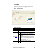
Enter the following parameters for linear motor mechanisms, if relevant.
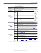
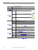
Table 109 - Linear Motor Properties
Parameters Description
Mechanism Type From the pull-down menu, choose the mechanism type.
Mechanism Data
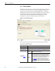
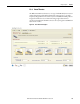
(label 1 in Figure 138)
The Load, Stroke, Speed, and Acceleration values are calculated based on the parameters entered in the previous Load and Profile
tabs and displayed here for reference.
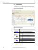
Orientation
(1)
(label 2 in Figure 138)
Horizontal Table
Mount
The actuator lies flat on a table.
Vertical Wall
Mount
The actuator moves up and down on a vertical wall.
Horizontal Wall
Mount
The actuator moves horizontally on a vertical wall.
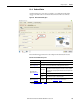
Configuration
(label 3 in Figure 138
)
Direct Drive Linear brushless motor.
Ball Screw Conventional rotary brushless motor driving a screw.
Cover An actuator cover provides protection from dust and dirt.
Overtravel Length
The addition length of travel at each end of the motion profile to allow for user-defined machine movements
outside of the motion profile (for example, setup of a mechanism or tool change spacing). It also allows room
for the stage to stop if it accidentally exceeds the nominal travel. Switches (physical or software) detect this
and the drive performs a controlled stop. Click the Axis Stop tab to determine the minimum stopping
distance required.
Actuator Stroke
From the Select Actuator Stroke pull-down menu, choose the required stroke length. If the option Automatic
is selected, the next largest value above Required Stroke + (2 x Overtravel) is selected. Larger sizes may be
selected at will if additional stroke is required for a function not considered in the motion profile.
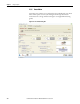
Constant Load
(label 4 in Figure 138)
Constant Mass
Any unchanging mass attached to the actuator. The actuator mass itself is automatically taken into account.
This value is editable in the Load Type Tab
on page 82.
External Force
Any unchanging force, other than gravity, acting on the load. It is also known as static force. This value is
editable in the Load Type Tab on page 82.
X, Y, and Z - Offset
These offsets allow for a load that has a center of gravity that is not close to the mounting plate of the
actuator. This value is significant for linear stage life calculations.
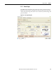
Profile Based
Loads
Any mass or force that changes during the cycle. The values must be entered for each segment of the motion
profile. These are entered in More Options Profile Editor Mode
, under the Profile toolbar.
Edit Payload Lets you quickly access More Options Profile Editor Mode
.
Payload
Animation
Displays a simple example of an application with a varying load.
(1) Only horizontal and vertical mounts are permitted corresponding to 0 and 90° inclination in the Load Type Tab on page 82. Any other inclination in the Load tab is converted to
horizontal mount.