
Software Owner manual

Rockwell Automation Publication MOTION-UM004B-EN-P - October 2012 183
Sizing Your System Chapter 2
2.3.4. Rack and Pinion
A rack and pinion is a rotary motor coupled to a toothed pinion wheel that
engages a toothed rack to create relative motion between the two elements.
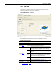
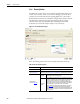
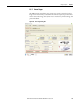
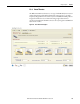
Figure 135 - Rack and Pinion Dialog Box
Enter the following parameters for rack and pinion mechanisms, if relevant.
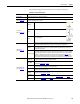
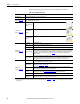
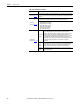
Table 106 - Rack and Pinion Properties
Parameters Description
Mechanism Type From the pull-down menu, choose the mechanism type.
Mechanism Data
(label 1 in Figure 135)
The Load, Stroke, Speed, and Acceleration values are calculated based on the parameters
entered in the previous Load and Profile tabs and displayed here for reference.
Pinion Application
(label 2 in Figure 135
)
Pinion PCD
Pinion Pitch Circle Diameter. The pitch circle diameter value can be
obtained from standard catalogue data. The value can also be calculated
by multiplying the tooth pitch by the number of teeth on the sprocket and
dividing by pi.
Inertia
(1)
(1) Use the Inertia Calculator Template on page 105 to calculate the inertia value for your application, if the value is not readily
available.
The inertia of the pinion.
Friction
Torque
The torque loss due to friction at the pinion shaft. This value can be
obtained from the supplier or Engineering tables.
Additional Loads
(label 3 in Figure 135
)
Table Mass
The mass of the linear load table. This mass is affected by gravity if the
inclination in the Load Type Tab on page 82 is non-zero.