
Software Owner manual

108 Rockwell Automation Publication MOTION-UM004B-EN-P - October 2012
Chapter 2 Sizing Your System
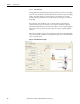
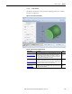
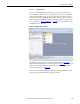
Figure 87 - Element Image Tab (label 3 in Figure 86)
Use this tab to verify the correct placement of the various inertia elements.
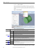
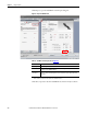
Element Properties
(label 2 in Figure 86)
Once the Element Properties are entered, the Element Mass and Element Inertia values are displayed at the bottom of the Element Properties window (label 4
in Figure 86
).
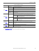
Type Select the type of element (solid cylinder, hollow cylinder, cuboid, or prism) you would like to add to the Element List.
Name Enter a meaningful name for the element you are editing.
Calculate Using Select the type of data (mass or density) you would like to use to calculate inertia.
X This is the position for the inertia element in the X (horizontal) direction. For a prism you will need to enter X1, X2 and X3 positions.
Y This is the position for the inertia element in the Y (vertical) direction. For a prism you will need to enter Y1, Y2 and Y3 positions.
Diameter This is the diameter of the inertia element if it is cylindrical. For a cuboid you will need to enter width and height.
Inner Diameter This is the inner diameter of the inertia element if it is a hollow cylinder.
Length This is the length of the inertia element. This parameter is not required when calculating based on mass.
Quantity This is the number of identical elements.
Mass This is the mass of the inertia element. This parameter is not required when calculating based on density.
Material
Select the material of the cylinder from the pull-down menu. If Other is selected as the material type, the density value also needs to be
entered. This parameter is not required when calculating based on mass.
Density
When the inertia element material is not available in the Material pull-down menu, the density value must be entered here. This
parameter is not required when calculating based on mass or when the material is selected from the pull-down menu.
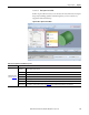
Element List
(label 5 in Figure 86
)
Summary list of the elements that make up the component with the current element highlighted in blue.
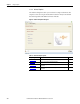
Results
(label 6 in Figure 86
)
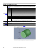
Motion Analyzer software takes gravity into account only if an unbalanced load is entered as secondary inertia. Gravity is taken to act from top to bottom of the
Component Plot window.
Error List In the event of incorrect input data, a list of errors is displayed.
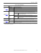
Table 64 - More Options Inertia Mode Properties (continued)
Parameter Description