User Manual Motion Analyzer Software Version 7.
Important User Information Solid-state equipment has operational characteristics differing from those of electromechanical equipment. Safety Guidelines for the Application, Installation and Maintenance of Solid State Controls (publication SGI-1.1 available from your local Rockwell Automation® sales office or online at http://www.rockwellautomation.com/literature/) describes some important differences between solid-state equipment and hard-wired electromechanical devices.
Summary of Changes This manual contains new and updated information. New and Updated Information This table contains the changes made to this revision. Topic Page Removed the Activation Wizard section. N/A Added Group/Ungroup and Add Drive Group descriptions to the Home Tab section. 16 Updated Power Data, Shunt, and Energy tab examples for the Power Supply/Accessories - Single-axis Drive Systems section. 46 Added Power Supply/Accessories – AC/DC Power Sharing Systems (Kinetix 5500 drives) section.
Summary of Changes Notes: 4 Rockwell Automation Publication MOTION-UM004B-EN-P - October 2012
Preface About This Publication The versatility of Motion Analyzer software lets users of various application complexities and experience levels use one software package to size their systems. This manual is designed to accommodate basic users, advanced users, and everyone in between. Who Should Use This Manual This manual is intended for engineers directly involved in the selecting, sizing, and optimizing of drives and motors or actuators for a motion control system.
Preface Notes: 6 Rockwell Automation Publication MOTION-UM004B-EN-P - October 2012
Chapter 1 Welcome to Motion Analyzer Software Topic Page Before You Begin Sizing 8 Database Updater Program 8 Welcome to Motion Analyzer 13 Menu Bar and Quick Access Toolbar 14 File Tab 15 Home Tab 16 Graphical View 17 Group View 22 Multiple Profile View 26 Power Supply/Accessories View 29 Preferences Tab 62 Export – Import Tab 65 Export to RSLogix 5000 Wizard 65 Bill of Materials (BOM) Tab 76 Help Tab 76 Explorer View 78 Rockwell Automation Publication MOTION-UM004B-EN-
Chapter 1 Welcome to Motion Analyzer Software 1.1. Before You Begin Sizing After downloading and starting Motion Analyzer software, you’ll want to update the Motion Analyzer database with the latest Allen-Bradley products available for motion control applications. This section steps you through that process. Download Motion Analyzer software from http://www.ab.rockwellautomation.com/motion-control/motion-analyzer-software. TIP 1.1.1.
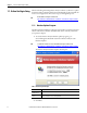
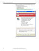
Welcome to Motion Analyzer Software Chapter 1 The program checks for database updates. If the program finds that you already have the current database installed, the following dialog box opens. 3. Click Finish.
Chapter 1 Welcome to Motion Analyzer Software 4. If the program finds that a database update is available, a dialog box opens with the following information: • • • • Installed software and database versions Available database version Database download file size Summary of new features and products in the new database 5. Click Update.
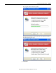
Welcome to Motion Analyzer Software Chapter 1 6. If the database updater program detects that your current version of Motion Analyzer software is running, a dialog box opens with the following instructions. 7.
Chapter 1 Welcome to Motion Analyzer Software 8. When the database updater program begins the update, this dialog box opens. 9. When the database updater program completes the update, this dialog box opens. 10. Click Finish.
Welcome to Motion Analyzer Software Chapter 1 1.1.2. Welcome to Motion Analyzer The Welcome to Motion Analyzer dialog box opens when the software application is launched. Two modes of operation are possible. Figure 1 - Welcome to Motion Analyzer Dialog Box Table 2 - Motion Analyzer Modes of Operation Mode Description Size and Select Intuitive workflow to help size, select, and optimize the motion control system. This mode also creates a bill of materials.
Chapter 1 Welcome to Motion Analyzer Software 1.2. Menu Bar and Quick Access Toolbar Your Motion Analyzer application file opens and the menu bar appears across the top of the dialog box. Above the menu bar is the Quick Access toolbar. Figure 2 - Size and Select Dialog Box Quick Access Toolbar Menu Bar The Quick Access toolbar provides shortcuts to commonly used functions. These functions include New, Open, Save, and Print.
Welcome to Motion Analyzer Software Chapter 1 1.2.1. File Tab The File tab is similar to the file menu in many computer applications. Figure 3 - File Tab Options Table 4 - File Tab Descriptions (refer to Figure 3) Options Description New Click New to go to the Welcome dialog box in Motion Analyzer software. Open Click Open to browse folders and open Motion Analyzer applications. Standard Open functionality. Save Click to save the running Motion Analyzer application. Standard Save functionality.
Chapter 1 Welcome to Motion Analyzer Software 1.2.2. Home Tab The Home tab contains five sections. Figure 4 - Home Tab Options Table 5 - Home Tab Descriptions Option Description Used to access the different views available in Motion Analyzer software. Views (label 1 in Figure 4) Clipboard (label 2 in Figure 4) Graphical View Click to open the Graphical view on page 17. Group View Click to open the Group view on page 22. Multiple Profile View Click to open the Multiple Profile view on page 26.
Welcome to Motion Analyzer Software Chapter 1 1.2.2.1. Graphical View The Graphical view applies to multi-axis drive families and provides graphical representation of the current (Bulletin 2093 and 2094) power rail and Kinetix 6000M integrated drive-motor system configurations.
Chapter 1 Welcome to Motion Analyzer Software 1.2.2.1.1. Power Rail View The Power Rail view displays the graphical representation of the current Bulletin 2093 or 2094 power rail configuration.
Welcome to Motion Analyzer Software Chapter 1 Figure 7 - Operations to Perform Example Additionally, you can click, drag, and drop a module to reposition that module on the power rail (refer to Figure 8).
Chapter 1 Welcome to Motion Analyzer Software 1.2.2.1.2. Power Interface Module View The integrated drive-motor power interface module (IPIM) mounts to the Bulletin 2094 power rail and connects (daisy-chains) with up to sixteen integrated drive-motor (IDM) units.
Welcome to Motion Analyzer Software Chapter 1 Figure 10 - Operations to Perform Example Additionally, you can click, drag, and drop an IDM unit to reposition that unit in the daisy-chain configuration (refer to Figure 11).
Chapter 1 Welcome to Motion Analyzer Software 1.2.2.2. Group View The Group view provides a summary of all the axes associated with the drive group. Additionally, the Group view gives a visual representation of the axis mapping in the power rail for multi-axes drive families. Group view varies depending on the Application mode selected. Refer to Figure 12 and Figure 13 for examples of each.
Welcome to Motion Analyzer Software Chapter 1 There are two areas of interest in the Group view, as illustrated in Figure 14. Figure 14 - Group View Example Table 9 - Power Rail View Options Options Description Page Power Rail Image (label 1 in Figure 14) Power rail image based on the current system configuration. This graphic only applies to multi-axis drive families.
Chapter 1 Welcome to Motion Analyzer Software 1.2.2.2.1. Power Rail Image The power rail image only applies to multi-axis drive families. In this example, the current configuration of Kinetix 6000 servo drives is shown on an eight-axis Bulletin 2094 power rail. Figure 15 - Bulletin 2094 Power Rail Image Table 10 - Power Rail Slot Example (refer to Figure 15) Option Description axis module (IAM) is always the first drive module on the power rail.
Welcome to Motion Analyzer Software Chapter 1 1.2.2.2.2. Axis Summary Image The axis summary images apply to all drive families. In this example, the current configuration of Kinetix 6000 servo drives includes the drive/motor combination featured below. Figure 16 - Axis Summary Bar (servo drive) Table 11 - Axis Summary Example Option Title Band (label 1 in Figure 16) Description Axis Solution Status Icon Axis Solution Status icon indicates the status of the selected solution.
Chapter 1 Welcome to Motion Analyzer Software 1.2.2.3. Multiple Profile View The Multiple Profile view permits viewing profiles of multiple axes simultaneously and defining axes synchronization and offsets among the axes. Figure 18 - Multiple Profile View Example Table 12 - Multiple Profile View Options 26 Options Description Page Top Band (label 1 in Figure 18) Lets you define the Time Span to which all graphs should be scaled.
Welcome to Motion Analyzer Software Chapter 1 1.2.2.3.1. Top Band This area lets you define the Time Span to which all graphs should be scaled. Additionally, this view lets you select a subset of the available axes to view. Figure 19 - Top Band of Multiple Profile View Table 13 - Top Band Example Option Description Modify Time Span (label 1 in Figure 19) Time span is the length of x-axis on which all the profiles are plotted. Use this option to zoomin or zoom-out on the time scale.
Chapter 1 Welcome to Motion Analyzer Software 1.2.2.3.2. Graph View The Graph view displays profiles of all axes with the shorter profiles being repeated to fit the length of the longest profile. Figure 21 - Graph View Example Table 14 - Graph View Options (refer to Figure 21) 28 Option Description Synchronized with The phase relationship between the various axis profiles in a common DC bus system affects the peak bus current requirement.
Welcome to Motion Analyzer Software Chapter 1 1.2.2.4. Power Supply/Accessories View In Axis view, you matched a drive with your motor. However, if there are power components needed for your application, you’ll select them in Power Supply/ Accessories view. 1.2.2.4.1. Power Supply/Accessories - Multi-axis Drive Systems If your drive family is Kinetix 2000, Kinetix 6000, or Kinetix 6200/6500, you’ll also need to configure the IAM module and select the appropriate power rail.
Chapter 1 Welcome to Motion Analyzer Software 1.2.2.4.1.1. Power Data Tab Use the Power Data tab to view regeneration and motoring data for each axis. Table 16 - Power Data Tab Properties (refer to Figure 22) 30 Parameters Description Axis Histograms The axis histograms show a multi-axis representation of axis currents including Peak Motoring, Average Motoring, Peak Regenerating, and Average Regenerating.
Welcome to Motion Analyzer Software Chapter 1 1.2.2.4.1.2. IAM and Shunt Tab Click Search to automatically configure the IAM and/or shunt module catalog number.
Chapter 1 Welcome to Motion Analyzer Software 1.2.2.4.1.3. IAM Control Power Tab The IAM Control Power tab displays total auxiliary input power, input VA, input current, and power distribution across the axes. These are the installation ratings for the IAM module. Figure 24 - IAM Control Power Tab Table 18 - IAM Control Power Tab Properties 32 Parameters Description Auxiliary AC Voltage (label 1 in Figure 24) Auxiliary AC Voltage is a user input value.
Welcome to Motion Analyzer Software Chapter 1 1.2.2.4.1.4. Analysis Tab Click Analysis to conduct detailed analysis of the drive module activity in terms of bus volts and system current, along with the capability of simulating changes to the system parameters. Figure 25 - Analysis Tab Dialog Box Table 19 - Analysis Tab Properties Parameters Description Simulation Parameters Adjust these parameters to observe how changes to the parameters impact the bus voltage and current.
Chapter 1 Welcome to Motion Analyzer Software 1.2.2.4.1.5. Energy Tab Click Energy to display the main power supply parameters including Input Current, System Power, Shunt Power and Energy Savings Estimates.
Welcome to Motion Analyzer Software Chapter 1 1.2.2.4.1.6. Configure Power Supply BOM Tab Click the Configure Power Supply BOM tab to complete the bill of materials (BOM) for the Power Supply after fully sizing the application. In this tab, you select options for the power rail, shunt module, filters, circuit breakers, and fuses.
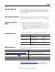
Chapter 1 Welcome to Motion Analyzer Software 1.2.2.4.1.7. System Bill of Materials (BOM) View Click BOM view to review the entire BOM (bill of materials) for the system and add any additional parts that may be needed. Table 20 - BOM View Tabs 36 Parameters Description Page Configuration Summary Tab Shows all the axis components in axis order. 37 Software and Accessories Tab Contains the Controllers, Software, and other Accessories to complete your system.
Welcome to Motion Analyzer Software Chapter 1 1.2.2.4.1.7.1. Configuration Summary Tab Click Configuration Summary to display all the axis components and descriptions in axis order. Scroll down to see all the axes.
Chapter 1 Welcome to Motion Analyzer Software 1.2.2.4.1.7.2. Software and Accessories Tab Click Software and Accessories to complete your system. To assist in selecting the Sercos cables, click Auto Select to automatically build a set of these cables with the required lengths to link the axes according to their slot configuration. Break-out boards, cables, kits, and various connectors are available to complete cabling from drive to motor.
Welcome to Motion Analyzer Software Chapter 1 1.2.2.4.1.7.3. Additional Parts Tab Click Additional Parts to add any additional components you may need. From the Product Family pull-down menu, choose the Family, Motor Series, and then by component category to reduce the time required to search for motion control components. If you know the catalog number, entering that is the quickest way to find your part.
Chapter 1 Welcome to Motion Analyzer Software 1.2.2.4.1.7.4. BOM Tab Click BOM to display the full bill of materials (BOM) in the same section headings as the other tabs. This BOM can be exported to Microsoft Word or Microsoft Excel software by clicking the appropriate button.
Welcome to Motion Analyzer Software Chapter 1 1.2.2.4.2. Power Supply/Accessories - Integrated Drive-Motor (IDM) Systems The integrated drive-motor (IDM) power interface module (IPIM) is effectively a power management module for the DC link to a group of individual IDM units, but to the 2094 power rail it looks like an axis module. Each IPIM module can handle up to 16 axes, with certain limitations.
Chapter 1 Welcome to Motion Analyzer Software Table 22 - Power Data Tab Descriptions Options Description Label 1 in Figure 26 Name of the power rail and selected IPIM module slot is displayed here. Click the power rail name label switches the view from IPIM view to Power Rail - Power Supply view. IDM Axis view (label 2 in Figure 26) Summary of the all IDM units associated with the selected IPIM module along with the Axis Motoring Bus Current and Axis Regenerating Bus Current values of each IDM unit.
Welcome to Motion Analyzer Software Chapter 1 1.2.2.4.2.3. Cable Length Tab Click the Cable Length tab to select cables for connecting IPIM module-to-IDM unit and IDM unit-to-IDM unit. Figure 28 - Cable Length Tab Table 24 - Cable Length Tab Descriptions Options Description From the Cable Length pull-down menus, choose the appropriate cable length for connecting IPIM module-to-IDM unit and IDM unit-to-unit.
Chapter 1 Welcome to Motion Analyzer Software 1.2.2.4.2.4. Control Power Tab Click the Control Power tab for utilization views and to select the number of sensor inputs and outputs. Figure 29 - Control Power Tab Table 25 - Control Power Tab Descriptions Options Utilizations (label 1 in Figure 29 Description Control Power This bar graph displays the percentage of power utilized by all IDM units to the maximum power that can be supplied by IPIM module.
Welcome to Motion Analyzer Software Chapter 1 Figure 31 - Control Power Tab (details revealed) 1.2.2.4.2.5. Configure IPIM Module BOM Tab Click the Configure IPIM Module BOM tab to select hybrid and network cables, and other IDM system accessory items. Figure 32 - Configure IPIM Module BOM Tab Table 26 - Configure IPIM Module BOM Tab Descriptions Options Description Step 1 (Figure 32) IPIM module IPIM module selected on the IPIM Module tab is displayed here.
Chapter 1 Welcome to Motion Analyzer Software 1.2.2.4.3. Power Supply/Accessories - Single-axis Drive Systems If your drive family is single axis, for example, Kinetix 300, Kinetix 350, Kinetix 3, or Ultra™3000, Ultra5000, and Ultra1500, you must configure a shunt or specify no shunt required.
Welcome to Motion Analyzer Software Chapter 1 1.2.2.4.3.1. Power Data Tab Use the Power Data tab to view regeneration and motoring data for each axis. Table 28 - Power Data Tab Properties (refer to Figure 34) Parameters Description Axis Histograms The axis histograms show a multi-axis representation of axis currents including Peak Motoring, Average Motoring, Peak Regenerating, and Average Regenerating. 1.2.2.4.3.2.
Chapter 1 Welcome to Motion Analyzer Software 1.2.2.4.3.3. Analysis Tab Click Analysis to display plots of drive module activity in terms of the DC bus voltage and DC bus current: • The red line is the bus voltage trip point. • The green line is the DC bus voltage. • The grey line is the bus current. Figure 36 - Analysis Tab Dialog Box Table 30 - Analysis Tab Properties Parameters Description Shunt On The voltage level where the shunt enables. Shunt Off The voltage level where the shunt turns off.
Welcome to Motion Analyzer Software Chapter 1 If the time slice variable is increased, this error message often appears. This time slice message may also appear as soon as you click Solution on the main taskbar. In this case, clicking Yes or No still takes you to the Solution tab, but if you click No, some pre-calculations are not performed. This time slice message often appears if one of the motion cycles is a cam, which often has very short time segments. In this case, click No to ignore the message.
Chapter 1 Welcome to Motion Analyzer Software 1.2.2.4.3.5. Configure Power Supply BOM Tab Click the Configure Power Supply BOM tab to complete the bill of materials (BOM) for the Power Supply after fully sizing the application. In this tab, you select options for the shunt module, filters, circuit breakers, and fuses.
Welcome to Motion Analyzer Software Chapter 1 1.2.2.4.4. Power Supply/Accessories – AC/DC Power Sharing Systems (Kinetix 5500 drives) If your drive family is Kinetix 5500, you must define a valid power sharing configuration and then configure a shunt and capacitor, or specify if no shunt or capacitor are required.
Chapter 1 Welcome to Motion Analyzer Software 1.2.2.4.4.1. DC Sharing Use the DC Sharing configuration to group axes to share a common DC bus and input AC supply (optional). Table 32 - Power Supply/Accessories Tabs (refer to Figure 37) Parameters Description Power Data Tab View regeneration and motoring data for each axis. Converter and Shunt Tab Select the shunts and capacitor for your system. Analysis Tab Analyze the drive module activity in terms of bus voltage and system current.
Welcome to Motion Analyzer Software Chapter 1 1.2.2.4.4.1.2. Converter and Shunt Tab Select shunt and capacitor modules for your system. Figure 39 - Converter and Shunt Tab Table 34 - Converter and Shunt Tab Properties (refer to Figure 39) Parameters Description Shunt Selection and Component Listing (label 1 in Figure 39) In this section you select a shunt for each axis, and a capacitor module for the system.
Chapter 1 Welcome to Motion Analyzer Software 1.2.2.4.4.1.3. Analysis Tab Click the Analysis tab to conduct detailed analysis of the drive module activity in terms of bus volts and system current, along with the capability of simulating changes to the system parameters. The analysis activities are described as follows: • The red line is the bus voltage trip point. • The green line is the DC bus voltage. • The grey line is the bus current.
Welcome to Motion Analyzer Software Chapter 1 If the time is increased, the time slice error message often appears. This time slice message may also appear as soon as you click Solution on the main taskbar. In this case, clicking Yes or No still takes you to the Solution tab, but if you click No, some pre-calculations are not performed. This time slice message often appears if one of the motion cycles is a cam, which often has very short time segments. In this case, click No to ignore the message. 1.2.
Chapter 1 Welcome to Motion Analyzer Software 1.2.2.4.4.1.5. Configure Power Supply BOM Tab Click the Configure Power Supply BOM tab to complete the bill of materials (BOM) for the power supply after fully sizing the application. In this tab, you select options for the power rail, shunt module, filters, circuit breakers, and fuses. Figure 42 - Configure Power Supply BOM Tab 1.2.2.4.4.2.
Welcome to Motion Analyzer Software Chapter 1 Table 36 - Power Supply/Accessories (refer to Figure 43) Parameters Description Power Data Tab View regeneration and motoring data for each axis. Converter and Shunt Tab Select the shunt and capacitor for your system. Analysis Tab Analyze the drive module activity in terms of bus voltage and system current. With this tab, you can also simulate changes to the system parameters.
Chapter 1 Welcome to Motion Analyzer Software 1.2.2.4.4.2.2. Shunt Tab Select the shunt and capacitor module for your system. Figure 45 - Shunt Tab Table 38 - Shunt Tab Properties (refer to Figure 45) 58 Parameters Description Shunt selection (refer to Figure 45) Click Search to configure external shunts if an existing internal shunt for a given drive is outside its rating. If you need more than one external shunt, click search to select multiple shunt modules.
Welcome to Motion Analyzer Software Chapter 1 1.2.2.4.4.2.3. Analysis Tab Click the Analysis tab to display plots of drive module activity in terms of the DC bus voltage and DC bus current. The analysis activities are described as follows: • • • The red line is the bus voltage trip point. The green line is the DC bus voltage. The grey line is the bus current.
Chapter 1 Welcome to Motion Analyzer Software If the time is increased, the time slice error message often appears. This time slice message may also appear as soon as you click Solution on the main taskbar. In this case, clicking Yes or No still takes you to the Solution tab, but if you click No, some pre-calculations are not performed. This time slice message often appears if one of the motion cycles is a cam, which often has very short time segments. In this case, click No to ignore the message. 1.2.
Welcome to Motion Analyzer Software Chapter 1 1.2.2.4.4.2.5. Configure Power Supply BOM Tab Click the Configure Power Supply BOM tab to complete the bill of materials (BOM) for the power supply after fully sizing the application. In this tab, you select options for the power rail, shunt module, filters, circuit breakers, and fuses.
Chapter 1 Welcome to Motion Analyzer Software 1.2.3. Preferences Tab The Preferences tab contains three sections. Figure 49 - Preferences Tab Options Table 40 - Preferences Tab Descriptions Options Database (label 1 in Figure 49) Settings (label 2 in Figure 49) Options (label 3 in Figure 49) Description My Preferred Database (refer to Figure 50) The product databases may be modified to restrict selections to those items marked by you.
Welcome to Motion Analyzer Software Chapter 1 Figure 51 - User Defined Motors Dialog Box Figure 52 - Options - User Information Dialog Box Rockwell Automation Publication MOTION-UM004B-EN-P - October 2012 63
Chapter 1 Welcome to Motion Analyzer Software Figure 53 - Options - Units of Measure Dialog Box Figure 54 - Options - Operating Conditions Dialog Box 64 Rockwell Automation Publication MOTION-UM004B-EN-P - October 2012
Welcome to Motion Analyzer Software Chapter 1 1.2.4. Export – Import Tab The Export - Import tab contains two sections. Figure 55 - Export - Import Tab Options Table 41 - Export - Import Tab Descriptions Options Description Project Data to Word Exports the application data to a Microsoft Word document. Profile Data Launches the export wizard to let you export the profile data of the selected axis. Refer to More Options Profile Editor Mode on page 142.
Chapter 1 Welcome to Motion Analyzer Software 1.2.4.1.1. Export Options - Create a New .L5X File 1. From the Export-Import menu, click Export To RSLogix 5000. The Output Format Selection dialog box opens. 2. Select Create a New L5X and from the pull-down menu and choose the RSLogix 5000 software version you intend to use. 3. Click Next. The Axis Mapping dialog box opens.
Welcome to Motion Analyzer Software Chapter 1 1.2.4.1.1.1. Axis Mapping Information about .L5X file that Motion Analyzer generates is displayed at the top of the screen as read only information. Table 42 - Axis Mapping Properties Attribute Description Controller Name Motion Analyzer software assigns a default name for the controller. You can edit this once the file has been loaded. Controller Type Motion Analyzer software creates a file with a default controller type.
Chapter 1 Welcome to Motion Analyzer Software Table 43 - Axis Mapping Symbols Attribute Description Axes will export without errors. Axes with warning icon only partially export to RSLogix 5000 software. A note at the bottom of the screen indicates what is wrong. Not recommended icon. A note at the bottom of the screen indicates what is wrong. If problems occur with selected catalog numbers, a warning icon and a note at the bottom of the dialog box appears.
Welcome to Motion Analyzer Software Chapter 1 The Target Location dialog box opens. 1.2.4.1.1.2. Save and Import the L5X File 1. Click Browse to select a target location and save the .L5X file. IMPORTANT Do not use spaces or special characters in the name, or RSLogix 5000 software will not open the file. 2. Click Finish.
Chapter 1 Welcome to Motion Analyzer Software 3. Open RSLogix 5000 software. 4. Browse to your .L5X file and open it.
Welcome to Motion Analyzer Software Chapter 1 5. Browse to the location where you would like to store your .acd file. 6. Click Import.
Chapter 1 Welcome to Motion Analyzer Software Your motion system information imports from Motion Analyzer software. Exceptions include warnings noted on the Axis Mapping dialog box.
Welcome to Motion Analyzer Software Chapter 1 1.2.4.1.2. Export Options - Update an Existing L5X File 1. From the Export-Import menu, click Export To RSLogix 5000. The Output Format Selection dialog box opens. 2. Select Update an Existing L5X and click browse to find the file you wish to update. 3. Click Next.
Chapter 1 Welcome to Motion Analyzer Software The Axis Mapping dialog box opens. 4. Make changes as needed to the existing file. 5. Click Next.
Welcome to Motion Analyzer Software Chapter 1 The Target Location dialog box opens. Table 44 - Export Output Target Properties Attribute Description Save Select Save to replace the old L5X file with the updated file. Save As Select Save As to create an updated L5X file in a new location and/or with a new name. 6. Open the file in RSLogix 5000 software as described earlier and notice that the motion system information from your Motion Analyzer software file has been included. 7. Click Finish.
Chapter 1 Welcome to Motion Analyzer Software 1.2.5. Bill of Materials (BOM) Tab The Bill of Materials (BOM) tab contains two sections. Figure 58 - Bill of Materials (BOM) Tab Options Table 45 - Bill of Materials (BOM) Tab Descriptions Options Configure (label 1 in Figure 58) Description Axis This is a combo item and contains the axis names of all the axes in the Drives Group that have a solution.
Welcome to Motion Analyzer Software Chapter 1 Figure 60 - Motion Analyzer Activation Wizard Figure 61 - About Motion Analyzer Rockwell Automation Publication MOTION-UM004B-EN-P - October 2012 77
Chapter 1 Welcome to Motion Analyzer Software 1.3. Explorer View The Explorer view provides a Windows Explorer style graphical user interface for accessing components in your Motion Analyzer software application. For multi-axis drive systems, the axes are added under the Power Rail node in the Explorer hierarchy view. Figure 62 - Typical Multi-axis Drive Explorer View For single-axis drive systems, the axes are added under the Project node in the Explorer hierarchy view.
Welcome to Motion Analyzer Software Chapter 1 Figure 64 - Typical AC/DC Power Sharing System (Kinetix 5500) Explorer View Table 47 - Explorer View Structure (refer to Figure 62) Options Description The project node contains two types of groups. The Power Rail/Drive Group (of the selected product family) and an unallocated group. Power Rail Node Drives Group Node Applies to drive families that allow AC and DC power sharing (Kinetix 5500). Shown is the drive group icon and drive name.
Chapter 1 Welcome to Motion Analyzer Software Notes: 80 Rockwell Automation Publication MOTION-UM004B-EN-P - October 2012
Chapter 2 Sizing Your System Topic Page Identify Your Load 82 Linear Loads 83 Rotary Loads 86 Rotary Complex Loads 87 Application Template Loads 96 From SolidWorks 120 Define Your Profile 139 Less Options Profile Editor Mode 140 More Options Profile Editor Mode 142 Specify Your Linear Load Mechanism 178 Belt Drive 180 Lead Screw 181 Chain and Sprocket 182 Rack and Pinion 183 Linear Motor 184 Electric Cylinders 186 Linear Stages 187 Linear Thrusters 189 Specify Your T
Chapter 2 Sizing Your System 2.1. Identify Your Load A load is a device that transfers the actuator output to the desired end effectors. Loads do not affect the motion type. Figure 65 - Load Type Tab Table 48 - Load Type Options 82 Load Type Description Page Linear Loads Load moves in a straight line. 83 Rotary Loads Load rotates and the system has no translation to linear motion. 86 Rotary Complex Loads Rotary motion can be translated to linear motion, and vise versa.
Sizing Your System Chapter 2 2.1.1. Linear Loads For a Linear application, the load moves in a straight line. Figure 66 - Linear Load Type Table 49 - Linear Load Parameters Parameter Description Load Mass Mass of the linear load. Applied Force Any external force (+/-) acting on the load. Positive force acts to oppose positive movement; down the inclination surface if inclination is non-zero. The arrow on the graphic indicates the force direction. Coeff of Friction Coefficient of friction (μ).
Chapter 2 Sizing Your System 2.1.1.1. Advanced Considerations - Counterbalances In a counterbalanced system, unbalanced mass should be entered as Table Mass and balanced mass as Belt/Chain Mass. Values for Table Mass, Belt/Chain Mass, and/or Slide Mass may be entered on the Mechanism tab (a future step in the workflow) if a Belt Drive, Lead Screw, Chain and Sprocket, or Rack and Pinion are selected. There are two main types of counterbalance.
Sizing Your System Chapter 2 2.1.1.1.1. Mass Counterbalance • Vertical load with a 100% mass counterbalance Set the Inclination field to zero and enter a load mass two times greater than the load into the Load Mass field. • Vertical load with less than 100% mass counterbalance. Set the Inclination field to zero and enter the load mass plus the counterbalance mass into the Load Mass field.
Chapter 2 Sizing Your System 2.1.2. Rotary Loads For a rotary application, the load rotates and the system has no translation to linear motion. Figure 68 - Rotary Load Type Table 51 - Rotary Load Parameters Parameter Description Primary Inertia (1) This is the inertia of any balanced load about the axis of rotation. For example, if the main mass is a circular table which is driven about its own axis of symmetry, then primary inertia is equal to the table inertia.
Sizing Your System Chapter 2 2.1.3. Rotary Complex Loads A complex rotary load is non-linear, which means that the load position is not directly proportional to the input shaft position as it is with standard actuator types. A simple example is a crank, where the load velocity is sinusoidal with a constant shaft speed. The Crank and Four Bar Linkage templates are available for these applications. The main challenge with non-linear mechanisms is that the inertia value varies with shaft angle.
Chapter 2 Sizing Your System Table 52 - Complex Load Data Options Option Complex Load Data (label 1 in Figure 69) Motion (1) (label 2 in Figure 69) Graph tab (label 3 in Figure 69) Description User Defined Import load data from an external file into the Complex Load Data table on page 90. Templates Use the Unbalanced Load and Crank templates to calculate load data and enter it in the Complex Load Data table on page 90.
Sizing Your System Chapter 2 In this Crank application, the green applied torque curve shows a sharp peak around 180° when a high force is encountered near the end of the linear stroke.
Chapter 2 Sizing Your System 2.1.3.1. User Defined For the User Defined data entry option, calculations are typically made with a spreadsheet. Once the data is arranged in columns to match the Complex Load Data table, you can copy the data to the clipboard and paste it into the table. The columns are tab delimited, which is the default format for Microsoft Excel software. Alternatively, you can create and import a text file.
Sizing Your System Chapter 2 2.1.3.2.1. Unbalanced Load Template This template lets you enter parameters for an unbalanced load application. Figure 73 - Unbalanced Load Template Motion Analyzer software assumes that the axis of rotation is parallel to the ground if no axis angle is entered and that unbalanced masses create a gravity related torque. Secondary Inertia, Secondary Mass and Axis Separation parameters are required to take into account gravity induced torque values.
Chapter 2 Sizing Your System If the gravity torque (Secondary Mass * 9.81 m/s2 * Axis separation2) is known to be small as compared to the acceleration torque or motor nominal torque, then it may not be necessary to include the unbalanced mass effects. ATTENTION: If the angle of movement in any profile segment is such that the gravity torque changes significantly during that segment (a common occurrence) then break the segment into smaller portions.
Sizing Your System Chapter 2 2.1.3.2.2. Crank Template The Crank template is used to calculate the load profile for a given application, based on either input shaft velocity or linear load velocity. IMPORTANT This template should only be used for constant inertia. Do not set secondary mass or secondary inertia when using this template.
Chapter 2 Sizing Your System Table 55 - Crank Template Parameters Parameter Description For reference to make sure that entered data is accurate and particularly that the orientation of the crank is correct. The animation rotates the crank so that the system can be better visualized. The X/Y plane is horizontal. Animated Display (label 1 in Figure 75) Template Options (inside red box in Figure 75) Vertical Slider (Left) Sets the crankshaft inclination.
Sizing Your System Chapter 2 Table 55 - Crank Template Parameters (continued) Parameter Results (label 4 in Figure 75) Chart Display (label 5 in Figure 75) Description Peak Inertia The calculated maximum reflected inertia at the crankshaft. Peak Ext. + Grav. Torque The Peak External Force + Gravity Torque is the calculated peak torque, generated from the external linear force and gravity. Apply Click to apply the load profile data and close the window.
Chapter 2 Sizing Your System 2.1.4. Application Template Loads The application templates let you enter pre-configured mechanism application data. Figure 77 - Application Template Load Type Table 56 - Application Template Options 96 Template Type Description Page Press Roll Feed (constant time/constant angle) This application is typically cutting strip material into pre-set lengths with a ‘Press Shear’ (heavy-duty knife).
Sizing Your System Chapter 2 2.1.4.1. Press Roll Feed (constant time/constant angle) This application is typically cutting strip material such as steel into pre-set lengths by means of a press shear (heavy-duty knife). The material must be stationary when the cut is made and the cut takes place over a fixed amount of time or a fixed angle of the driving crank whose speed is varied to match the cut rate.
Chapter 2 Sizing Your System Table 57 - Press Roll Feed Parameters Parameter Load (label 1 in Figure 78 or Figure 79) Description Moving Material Mass The mass of the material in the loop and on the flat before the Nip/Feed rolls. (3) Bias Force The force required to overcome the force of gravity on the loop. (3) Drive Roll Diameter Total Roll Inertia (2) The diameter of the roll in direct contact with the strip, driven from the motor. The total inertia of the strip material at the drive shaft.
Sizing Your System Chapter 2 Click in Figure 78 or Figure 79 to determine the Moving Mass and Bias Force parameters by using the Loop Calculator. Figure 80 - Loop Calculator Table 58 - Loop Calculator Parameters Parameter Material (label 1 in Figure 80) Loop (label 2 in Figure 80) Computed Parameters (label 3 in Figure 80) Description Density Choose strip material from the pull-down menu or enter the density value manually. Thickness Strip material thickness. Width Strip material width.
Chapter 2 Sizing Your System 2.1.4.2. Carriage Cut Off This application is typically cutting strip material such as steel into pre-set lengths by means of a Flying Shear (heavy-duty knife mounted on a moving carriage). The shear must be stationary relative to the material (for example, moving at line speed) when the cut is made and the cut takes a fixed time. Strip material is unwound from a reel at constant surface speed and fed via separately driven leveler rolls.
Sizing Your System Chapter 2 Table 59 - Carriage Cut Off Parameters Parameter Load (label 1 in Figure 81) Description Mass of Carriage Total mass of the linear moving parts. Drive Roll Diameter Diameter of the roll, driven from the motor. Friction Coefficient Coefficient of friction of the sliding bearing. Cut Time Time the carriage must be synchronized accurately with the material.
Chapter 2 Sizing Your System 2.1.4.3. Cutter Knife Drive This application is typically cutting strip material such as steel into pre-set lengths by means of a rotary knife (heavy-duty knife blades mounted on a pair of rotating drums). The blades must be stationary relative to the material (for example, moving at line speed) when the cut is made and the cut takes place over a fixed drum angle. Strip material is unwound from a reel at constant surface speed and fed via separately driven leveler rolls.
Sizing Your System Chapter 2 Table 60 - Cutter Knife Drive Parameters Parameter Load (label 1 in Figure 82) Description Total Knife Inertia (2) Inertia of the knife assembly at the drive shaft. Effective Diameter As illustrated in the Cutter Knife Drive (Rotary Knife) diagram, this is the diameter of the circle passing through the cutting edge. Contact Angle (Before BDC) Time the material must be stationary in an accurate position.
Chapter 2 Sizing Your System 2.1.4.4. Advanced Templates The Advanced Templates tab let you enter data for complex mechanisms. The templates convert the complex mechanisms into Motion Analyzer mechanism data and load profiles with additional inertia and loads. Figure 83 - Advanced Templates Dialog Box Table 61 - Advanced Template Options 104 Template Type Description Page Inertia Calculator Calculates the inertia for your application.
Sizing Your System Chapter 2 2.1.4.4.1. Inertia Calculator The Inertia Calculator has several options for inputting parameters to calculate inertia for an application. Figure 84 - Inertia Calculator Template Table 62 - Inertia Calculator Template Options Template Type Description Page Less Options Inertia Mode This is the default mode when you open the Inertia Calculator. You can also enter this mode by clicking Less Options in the lower left corner of the calculator in More Options Inertia Mode.
Chapter 2 Sizing Your System 2.1.4.4.1.1. Less Options Inertia Mode The Less Options Inertia mode is the default mode when you open the Inertia Calculator. Use this mode to calculate inertia for a single cylindrical component. The center of mass/center of gravity of the cylinder must coincide with the axis of rotation.
Sizing Your System Chapter 2 2.1.4.4.1.2. More Options Inertia Mode In More Options Inertia mode you can calculate the mass and inertia of complex shapes. By assembling cylinders, cuboids and prisms, you can construct any largely three dimensional shape. Figure 86 - More Options Inertia Mode Table 64 - More Options Inertia Mode Properties Parameter Description Add Element Pull-down menu that lets you add an inertia element at the bottom of the Element List.
Chapter 2 Sizing Your System Table 64 - More Options Inertia Mode Properties (continued) Parameter Description Once the Element Properties are entered, the Element Mass and Element Inertia values are displayed at the bottom of the Element Properties window (label 4 in Figure 86). Type Select the type of element (solid cylinder, hollow cylinder, cuboid, or prism) you would like to add to the Element List. Name Enter a meaningful name for the element you are editing.
Sizing Your System Chapter 2 2.1.4.4.1.3. SolidWorks Import You can use the SolidWorks Inertia Calculator to import inertia data directly from SolidWorks software when the part geometry is complex and a SolidWorks model is readily available. The part must be balanced about the axis of rotation. For unbalanced loads, a SolidWorks Motion Study must be completed and users must interface with SolidWorks, using the resulting torque data to appropriately size a motor.
Chapter 2 Sizing Your System Click Import to open the SolidWorks - Data Import dialog box. Figure 89 - Import SolidWorks Data Table 65 - SolidWorks - Data Import (refer to Figure 89) Parameter Description Load/Change Load or change the SolidWorks model. Refresh Update the data returned to Motion Analyzer software if changes are made to the model while the part is open in SolidWorks software.
Sizing Your System Chapter 2 The SolidWorks – Data Import window closes and returns to the Inertia Calculator window and the imported element image.
Chapter 2 Sizing Your System 2.1.4.4.2. Winder/Unwinder Use this template to enter required inputs to calculate the load profile for Winder or Unwinder applications.
Sizing Your System Chapter 2 Table 66 - Input Data (label 1 in Figure 91) Parameter Description Center Driven The roll is driven directly via a shaft at its center of rotation. For a Center Driven application, Rotary Load is selected and the roll is modeled as Inertia and Torque in a Multi-segment profile. No further load information needs be added. The roll is driven by the friction of rollers pressing onto the circumference of the web.
Chapter 2 Sizing Your System 2.1.4.4.3. Four Bar Linkage You can use this template to enter required inputs to calculate the load profile for Four Bar Linkage applications. Figure 92 - Four Bar Linkage Template Figure 93 - Animated Diagram (for reference) TIP 114 Parameter entry descriptions are displayed when the cursor is held over an entry field for several seconds.
Sizing Your System Chapter 2 Table 68 - Four Bar Linkage Properties Parameter Animated Display (1) (label 1 in Figure 92) Mechanical Data (label 2 in Figure 92) Description Vertical Slider (left) This slider sets the crankshaft inclination and should be set before starting the animation. Click 0y to set the angle to 90°. The current angle is displayed in the Mechanical Data window. Horizontal Slider (top) This slider sets the linear slide inclination. Click 0z to set the angle to 0°.
Chapter 2 Sizing Your System Table 68 - Four Bar Linkage Properties (continued) Parameter Description Coarse Data Select this option if the size of the profile segments is sufficient to detect significant changes to force or inertia during each time slice. Fine Data Select this option if a finer resolution of the profile segments is needed to detect significant changes to force or inertia during each time slice. You can copy spreadsheet data and paste into this grid.
Sizing Your System Chapter 2 Click to use the Quick Profile tool. A trapezoidal load profile is entered into the data grid after clicking Apply. Figure 94 - Quick Profile Tool Table 69 - Quick Profile Tool (refer to Figure 94) Parameter Description Move Angle Angle through which the load profile takes place. Move Time Time through which the load profile takes place. Wait Time Length of time to wait before the specified index move repeats. Velocity Pk/Ave Velocity Peak/Average.
Chapter 2 Sizing Your System 2.1.4.5. Power/Speed Templates You can use the Power/Speed templates to enter torque and speed values that are used to calculate the power requirements for the application. Figure 95 - Power/Speed Templates Table 70 - Power/Speed Template Options 118 Template Type Description Page Power/Speed Template (label 1 in Figure 95) Use this template when the torque and speed values are known at the load for the application.
Sizing Your System Chapter 2 2.1.4.5.1. Power/Speed Template Use this template (label 1 in Figure 95) when the torque and speed values are known for the application. Click to access the Power Calculator. Figure 96 - Power Calculator Table 71 - Input Properties (refer to Figure 96) Parameter Description Torque Torque value for your application. Speed Speed for your application.
Chapter 2 Sizing Your System 2.1.4.5.2. Constant Power Range Template Use this template (label 2 in Figure 95) when three of the following four values are known for the application. Click values. to use the Power Calculator and enter the known torque and speed Figure 97 - Power Calculator Table 72 - Input Properties (refer to Figure 97) Parameter Description Max Torque Maximum torque value for your application. Min Torque Minimum torque value for your application.
Sizing Your System Chapter 2 Each load type requires a slightly different workflow in Motion Analyzer software to obtain the data from SolidWorks software. Both workflows support linear and rotational motion. IMPORTANT A SolidWorks Assembly must be open in SolidWorks software when launching the SolidWorks Interface Wizard from Motion Analyzer software. IMPORTANT A SolidWorks Motion Study must be set up before launching the SolidWorks Interface Wizard.
Chapter 2 Sizing Your System 2.1.5.1. Independent Axis Workflow With independent motors, each motor works alone to move the load in the single-axis, independent workflow, so the force/torque output stands isolated. An example is the single-axis lifter mechanism (Figure 98) where one motor drives the load. Figure 98 - Independent Motors SolidWorks Motion software supports linear and rotary motors.
Sizing Your System Chapter 2 Follow these steps for an independent axis workflow. 1. Click the Load tab. Select Translational (Linear) if a linear load is defined or Rotational (Rotary) if a rotary load is defined in the SolidWorks Motion Study. 2. Click Next.
Chapter 2 Sizing Your System 3. Click Edit Profile to specify the motion profile that the mechanism will move through. This motion profile is placed at the output of the motor or gearbox shaft, if a gearbox is included in the motion system. Refer to Define Your Profile on page 139 for more information. Once you specify the motion profile for the axis, the SolidWorks integration begins. 4. Click Launch SolidWorks Simulator to obtain force/torque results from SolidWorks software.
Sizing Your System Chapter 2 The Selected SolidWorks Assembly dialog box opens. 5. Verify the following conditions: • The SolidWorks assembly must be open in SolidWorks software before the SolidWorks integration wizard is launched. • The SolidWorks file must be an assembly and not simply a part. • Only one instance of SolidWorks software can be running in order for integration to work. 6.
Chapter 2 Sizing Your System The Motion Study Setup dialog box opens. 8. From the Motion Study Name pull-down menu, choose a SolidWorks Motion Study for the data. 9. Click Next. If you need to create a new motion study, return to SolidWorks software. a. Return to the opening window and click Refresh to register the changes. b. Click Next.
Sizing Your System Chapter 2 The SolidWorks Motor Setup dialog box opens. This dialog box lets you verify the SolidWorks Motor Setup. For interdependent motors, you assign Motion Analyzer motion profile data to each SolidWorks motor during this step. The Motor Setup dialog box is repeated for each axis of motion. 10. From the Motion Analyzer Axis pull-down menu, choose the Motion Analyzer axis.
Chapter 2 Sizing Your System The Summary dialog box opens. 14. Enter a value in the Frames/Second field. This value indicates the number of frames per second the motion profile is divided into. A large number yields fine resolution while a small number yields coarse resolution. 15. Click Modify Selections. Use this feature to edit a specific Motion Analyzer Axis. a. Select an axis in the table. b. Click Modify Selections to jump back to the SolidWorks Motor Setup window for the selected axis. 16.
Sizing Your System Chapter 2 SolidWorks software calculates the force/torque required to move the load through the specified motion profile and the Results dialog box opens. 17. From the Results pull-down menu, choose the axis of motion you wish to display. 18. Click the View Graph tab. This tab displays the data in graphical format. 19. Click the View Data tab. This tab displays the data in list format. 20. Click Export Data. The data exports into a spreadsheet. 21.
Chapter 2 Sizing Your System The SolidWorks Load Data dialog box opens. This dialog box lets you compare the actual Motion Analyzer velocity profile to the velocity profile returned from SolidWorks. 24. Check Invert SolidWorks Output Data if the velocity profiles were reversed to resolve the discrepancy and correct your model. The discrepancy is due to different coordinate systems, which are arbitrarily defined. 25. Click Proceed to Transmissions. This step changes depending upon the application.
Sizing Your System Chapter 2 2.1.5.2. Inter-dependent Axes Workflow With inter-dependant motors, several motors work to move one load, so although the motors have separate force/torque outputs, they depend on each other to collectively move the load. An example is the two-axis linear pick and place mechanism (Figure 99) where two motors drive the load. Figure 99 - Inter-dependant Motors Once the motion profile for each axis has been specified, the SolidWorks integration begins.
Chapter 2 Sizing Your System The Selected SolidWorks Assembly dialog box opens. 2. Verify the following conditions: • The SolidWorks assembly must be open in SolidWorks software before the SolidWorks integration wizard is launched. • The SolidWorks file must be an assembly and not simply a part. • Only one instance of SolidWorks software can be running in order for integration to work. 3.
Sizing Your System Chapter 2 The Motion Study Setup dialog box opens. 5. From the Motion Study Name pull-down menu, choose the SolidWorks motion study to be used for simulation. If you need to create a new motion study, return to SolidWorks. Return to the opening dialog box and click Refresh to register the changes. 6. Click Next.
Chapter 2 Sizing Your System The SolidWorks Motor Setup dialog box opens. 7. Enter the number of axes you would like to study. Motion Analyzer detects the number of SolidWorks motors present in the chosen SolidWorks motion study. IMPORTANT The number of Motion Analyzer axes to be studied must be less than or equal to the number of SolidWorks motors. Also, the number of motion profiles sent to SolidWorks software cannot exceed the number of SolidWorks motors waiting to consume the motion profile data.
Sizing Your System Chapter 2 The SolidWorks Motor Setup dialog box opens. This dialog box lets you verify the SolidWorks Motor Setup. For interdependent motors, you assign Motion Analyzer motion profile data to each SolidWorks motor during this step. The Motor Setup dialog box is repeated for each axis of motion. 9. From the Motion Analyzer Axis pull-down menu, choose the Motion Analyzer axis.
Chapter 2 Sizing Your System The SolidWorks Summary dialog box opens. 13. Enter a value in the Frames/Second field. This value indicates the number of frames per second the motion profile is divided into. A large number yields fine resolution while a small number yields coarse resolution. 14. Click Modify Selections. Use this feature to edit a specific Motion Analyzer Axis. a. Select an axis in the table. b. Click Modify Selections to jump back to the SolidWorks Motor Setup window for the selected axis.
Sizing Your System Chapter 2 SolidWorks software calculates the force/torque required to move the load through the specified motion profile and the Results dialog box opens. 16. From the Results pull-down menu, choose the axis of motion you wish to display. 17. Click the View Graph tab. This tab displays the data in graphical format. 18. Click the View Data tab. This tab displays the data in list format. 19. Click Export Data. The data exports into a spreadsheet. 20.
Chapter 2 Sizing Your System The System View dialog box in Motion Analyzer software opens. 23. Click the Motor and Drive icons to continue the sizing process. With these versions of SolidWorks and Motion Analyzer software, the inertia data is not brought out automatically. This means that Motion Analyzer has no knowledge of the inertia ratio and therefore cannot do the Motion Analyzer Simulation on the Solution tab.
Sizing Your System 2.2. Define Your Profile Chapter 2 There are two ways to enter your Motion Profile into Motion Analyzer software. Begin by clicking Edit Profile in the Cycle Profile Data dialog box. Table 74 - Motion Profile Options Template Type Description Page Less Options Profile Editor Mode This is the default mode. This mode is also accessed by clicking Less Options in the More Options Profile mode.
Chapter 2 Sizing Your System 2.2.1. Less Options Profile Editor Mode The Less Options Profile mode is the default mode. This mode is also accessed by clicking Less Options when in the More Options Profile mode. Figure 100 - Simple Index Motion Parameters When using this mode to enter motion profile data, a trapezoidal velocity index profile segment (see Automatic Index Type below) is the default motion profile. This motion profile is optimized for minimal motor heating.
Sizing Your System Chapter 2 Table 75 - Less Options Profile Editor Properties Parameter Description Reset Zoom (1) Resets the zoom to 1x. Zoom (1) Magnifies 1x, 2x, 6x, or 8x. Grid Segment Plot (refer to label 2 in Figure 100 and the example in Figure 101) (1) Color Select Normal, Fine or Remove Grid to change the display. (1) Show Curve Adjust the background, curve and grid colors. (1) Select which curves you would like to display on the plot.
Chapter 2 Sizing Your System 2.2.2. More Options Profile Editor Mode The More Options Profile Editor mode helps you create a variety of industrystandard motion profiles. To access this mode, click More Options when in the Less Options Profile mode. Figure 102 - Profile Editor - More Options Mode These windows are displayed by default when you open the More Options Profile Editor Mode.
Sizing Your System Chapter 2 In addition to the windows that are opened by default, there are several tabs along the bottom (label 6 in Figure 102) and left side (red arrow in Figure 102) of the More Options Profile Editor Mode that open other windows. Table 77 - Additional More Options Mode Features Feature Description Page Profile Grid Lets you quickly input parameters into a table for each segment of your motion profile.
Chapter 2 Sizing Your System You also have the option to import motion profile data from external programs. The following import options are available. Table 79 - Import Options (refer to Figure 102) Feature Feature Description This option lets you import motion profiles created in the RSLogix 5000 Cam Editor. A Logix Elements type profile segment is created and populated. You have four import options available for this type of import.
Sizing Your System Chapter 2 2.2.2.1. Profile Toolbar The Profile toolbar contains buttons and pull-down menus for adding, moving, and removing profile segments or an entire motion profile. Figure 103 - Profile Toolbar Features Table 80 - Profile Toolbar Features (label 1 in Figure 103) Feature Description Segment Selector Use the Segment Selector arrows (red box in Figure 103) to navigate through the various segments in your motion profile.
Chapter 2 Sizing Your System Figure 104 - Add Feature Pull-down Menu Table 81 - Add Feature Properties (refer to Figure 104) 146 Feature Description Edit Lets you change the selected profile segment to another segment type. Delete Deletes the selected profile segment. You can also click the drop-down arrow and select the Delete All option to delete all of the segments in your motion profile.
Sizing Your System Chapter 2 2.2.2.2. Segment Load Window Each profile segment type has an associated Segment Parameters window (label 2 in Figure 102. As you highlight a particular profile segment in your motion profile, that segment’s parameter window becomes available for entering data. The default profile segment type is an Index profile segment.
Chapter 2 Sizing Your System 2.2.2.3. Segment Plot Window The Segment Plot window displays a plot for a single profile segment in the motion profile. The x-axis is time, and the y-axis can be adjusted to display various motion curves (for example, Distance, Velocity, or Acceleration). Figure 107 - Profile Editor - Segment Plot Window Right-click the Segment Plot window to display the properties.
Sizing Your System Chapter 2 2.2.2.4. Profile Plot The Profile Plot window lets you view the entire motion profile and quickly navigate to specific segments within the profile. Figure 109 - Profile Editor - Main Profile Plot Right-click the Main Profile Plot window to display the properties.
Chapter 2 Sizing Your System Table 84 - Main Profile Plot Properties (refer to Figure 110) Parameters Description Copy Create a copy of the selected profile segment to reuse in another location in the motion profile. Cut Remove the selected profile segment to use in another location in the motion profile. Paste Replace the selected profile segment with a cut or copied profile segment. Delete Deletes the selected profile segment.
Sizing Your System Chapter 2 Figure 112 - Main Profile Plot X and Y-axis Values The Profile Zoom Plot sub-window appears below the Main Profile Plot window. Click the arrows, below the Main Profile Plot window, to open it. Click the arrows again to close the window. The Profile Zoom Plot window contains a slider (refer to the red box in Figure 113) that you can move along the motion profile by clicking and dragging it.
Chapter 2 Sizing Your System 2.2.2.5. Profile Grid Click Profile Grid (label 5 in Figure 115) to use a table to input parameters for each segment of your motion profile. Figure 115 - Profile Grid Window If you click a row in the Profile Grid window, the Segment Parameter window and the plot for that profile segment are opened at the top of the More Options Profile Editor Mode dialog box. You have the option to enter the parameters in the Segment Parameters window or the Profile Grid.
Sizing Your System Chapter 2 2.2.2.6. Derived Parameters Click Derived Parameters (label 5 in Figure 116) to display various calculated values related to Time, Position, Speed, Acceleration, and Jerk for the highlighted profile segment. Refer to the Segment Parameters windows on page 167 to adjust these values.
Chapter 2 Sizing Your System 2.2.2.7. Comments Window Click Comments (label 5 in Figure 117) to enter notes about the overall motion profile in the Profile Comments window. For specific profile segments in the last comment of the table labeled Segment Comments. Highlight the row for a particular profile segment and the segment plot is displayed at the top of the More Options Profile Editor Mode dialog box.
Sizing Your System Chapter 2 2.2.2.8. Error List Window Click Error List (label 5 in Figure 118) to display errors in the Error List window. Errors are listed as they occur. Figure 118 - Error List Window An example of a common error is a negative value for time in Absolute mode.
Chapter 2 Sizing Your System 2.2.2.9. Profile Export When you have completed your motion profile and have entered the relevant parameters, you can export the data from the More Options Profile Editor Mode to external programs. Prior to exporting the data, make sure that the master and slave units are properly designated. From the menu bar go to Settings>Custom Units to change these. The Profile Export wizard is designed to help you successfully export your profile. 1.
Sizing Your System Chapter 2 Table 86 - Type of Export Options Parameters Description Page Logix CAM Profile Editor With this option you can export the motion profile data to RSLogix 5000 software as a fixed cam profile. When using this export option, you choose whether to export the data as a Motion Axis Time Cam (MATC) or a Motion Axis Position Cam (MAPC).
Chapter 2 Sizing Your System The Export Options - Logix CAM dialog box opens and a preview of the data for export is displayed. 5. Click Next. The Target Location for Export dialog box opens. 6. Select how you would like to store the data. Table 87 - Target Location Options Parameters Description Clipboard The clipboard stores the data until you copy something else and it is useful if you are going to paste the data into RSLogix 5000 software immediately.
Sizing Your System Chapter 2 The Profile Export Successful dialog box opens. TIP If the Start and End Slope values are non-zero in your application, enter them into the Cam Editor manually. 8. Click Finish. 9. Open your RSLogix 5000 software application program to your MATC instruction. 10.
Chapter 2 Sizing Your System The Cam Editor dialog box opens. 11. Right-click the first row entry arrow and from the window choose Paste. Your move data appears in the Cam Editor dialog box. TIP Click the magnifier icon to adjust the zoom. 12. Click OK.
Sizing Your System Chapter 2 2.2.2.9.2. Logix Ladder Add-On Instructions To use this function it is necessary to have the following suite of cam-building Add-On Instructions installed with your RSLogix 5000 project: Table 88 - CAM-building Add-On Instructions File Name AOI_CG_00_Import_then_delete_this.L5X AOI_CG_00_Controller_Tags.CSV Description Add-On Instructions files AOI_CG_00_Cam Generator Setup.doc Installation instructions Cam_Generator_V2_1_Example.ACD Generic (blank) project file 1.
Chapter 2 Sizing Your System The Export Options - Logix Ladder dialog box opens. 5. Click Next. The Target Location for Export dialog box opens. 6. Select how you would like to store the data. Table 89 - Target Location Options Parameters Description Clipboard The clipboard stores the data until you copy something else and it is useful if you are going to paste the data into RSLogix 5000 software immediately.
Sizing Your System Chapter 2 The Profile Export Successful dialog box opens. TIP If the Start and End Slope values are non-zero in your application, enter them into the Cam Editor manually. 8. Click Finish. 9. Open your RSLogix 5000 software application program and paste the data into an empty rung. IMPORTANT Make sure the entry type is In Neutral Text.
Chapter 2 Sizing Your System The Add-On Instruction appears on the rung. In this example, the Add-On Instruction is a simple index move.
Sizing Your System Chapter 2 2.2.2.9.3. SolidWorks Motion Study Move Profile 1. On the Types of Exports dialog box, select SolidWorks Motion Study Move Profile. This is not the preferred workflow. A direct link using API calls has been developed and is described in From SolidWorks on page 120. 2. Click Next. The Export Options - SolidWorks dialog box opens. 3. Define the number of segments you would like to export the data in.
Chapter 2 Sizing Your System 2.2.2.9.4. User Defined 1. On the Types of Exports dialog box, select User Defined. 2. Click Next. The Export Options - User Defined dialog box opens. 3. Select the unit options. You can export data in your application units or in SI units. In this example, application units are chosen. 4. From the pull-down menu, choose the delimiter. In this example, TAB was chosen. TAB delimited is a standard format for Microsoft Excel software. 5. Click Next.
Sizing Your System Chapter 2 2.2.2.10. Segment Parameters Window Each profile segment type has a different associated Segment Parameters window. The default profile segment type is an Index profile segment (label 2 in Figure 120). Figure 120 - Segment Parameters The following basic profile segments are available in the More Options Profile Editor Mode dialog box. Table 90 - Basic Profile Segment Options Parameters Description Page Start Condition Sets the start conditions for your motion profile.
Chapter 2 Sizing Your System 2.2.2.10.1. Start Condition Start Condition (refer to Figure 120) sets the start conditions for your motion profile. The start condition is the initial time, position, and velocity of the motion profile. Figure 121 - Start Condition Dialog Box Enter the following parameters for the Start Condition, if relevant. Table 92 - Start Condition Properties Parameters Description Time The initial time that the motion profile begins.
Sizing Your System Chapter 2 Enter the following parameters for Acceleration/Deceleration, if relevant. Table 93 - Acceleration/Deceleration Properties Parameters Description Segment Name Enter a meaningful name for the profile segment. Data Entry Permutation Select an option for entering the profile segment parameters based on two data types (for example, Time and Distance or Time and Velocity). Increment/Absolute Select whether to input Incremental or Absolute parameter values.
Chapter 2 Sizing Your System 2.2.2.10.3. Cruise/Dwell The profile segment is considered a cruise if the velocity at the end of the previous profile segment is non-zero and is considered a dwell if that velocity is zero. Figure 124 - Cruise/Dwell Dialog Box Enter the following parameters for a Cruise/Dwell profile segment, if relevant. Table 94 - Cruise/Dwell Properties 170 Parameters Description Segment Name Enter a meaningful name for the profile segment.
Sizing Your System Chapter 2 2.2.2.10.4. Index An Index profile segment consists of an acceleration, a cruise, and a deceleration. Figure 125 - Index Motion Parameters Dialog Box Enter the following parameters for a Index profile segment, if relevant. Table 95 - Index Properties Parameters Description Segment Name Enter a meaningful name for the profile segment. Increment/Absolute Select whether to input Incremental or Absolute parameter values.
Chapter 2 Sizing Your System Figure 126 - Trapezoidal Profile Parameters Description Used to decrease the discontinuity in the transition from a dwell to motion. Select the smoothness from the pull-down menu. Three smoothness options are available.
Sizing Your System Chapter 2 2.2.2.10.5. Index Advance Index Advance selects more advanced velocity, acceleration, and jerk profiles for an Index profile segment. Figure 127 - Index Advance Parameters Dialog Box Enter the following parameters for a Index Advance profile segment, if relevant. Table 96 - Index Advance Properties Parameters Advance Index Type Description Index SHM Harmonic Motion. Index 3 4 5 Poly Fifth order polynomial. Index Mod Sine Modified Sine wave.
Chapter 2 Sizing Your System 2.2.2.10.6. Logix Element Use this dialog box to import or export Logix elements into RSLogix 5000 software. Figure 128 - Logix Element Dialog Box The Logix Element Motion Parameter table is essentially the same as the RSLogix 5000 cam editor.
Sizing Your System Chapter 2 Enter the following parameters for a Logix Element profile segment, if relevant. Table 97 - Logix Element Properties Parameters Description Segment Name Enter a meaningful name for the profile segment. Master This is directly equivalent to the Master column in RSLogix 5000 software. These values can be entered only as Master and Slave Custom Units. From the Settings menu, choose Custom Units to change these.
Chapter 2 Sizing Your System 2.2.2.10.7. Motion Axis Move (MAM) This window lets you enter data as if for a Motion Axis Move (MAM) instruction. For detailed information regarding a MAM, refer to the RSLogix 5000 software help files. Figure 129 - MAM Dialog Box Enter the following parameters for a MAM profile segment, if relevant. Table 99 - MAM Instruction Properties 176 Parameters Description Position Units Select the required position units in the pull-down menu above the MAM profile segment.
Sizing Your System Chapter 2 Click More and enter the following parameters for a MAM profile segment, if relevant. Table 100 - More MAM Instruction Properties Parameters Description Accel Rate This is the acceleration rate for the MAM profile segment. Accel Units These units cannot be adjusted here. To change the units, choose an option from the Position Units pull-down menu at the top of the MAM Segment Parameters window. Decel Rate This is the deceleration rate for the MAM profile segment.
Chapter 2 Sizing Your System 2.3. Specify Your Linear Load Mechanism A linear load mechanism is used to convert rotary motor torque to linear motion through a transmission (belt drive, lead screw, chain and sprocket, or rack and pinion), where thrust from a linear motor, electric cylinder, or linear stage produces linear motion directly. Figure 130 - Mechanism Type The following mechanisms are available in Motion Analyzer software.
Sizing Your System Chapter 2 In addition to the many linear mechanisms in Table 101, a few fully-integrated linear mechanisms, listed in Table 104, are also included. Figure 131 - Integrated Linear Mechanisms Table 102 - Additional Mechanism Types Linear Options Description Page Electric Cylinders These electric cylinders provide flexible, digital servo control of a rod actuator (linear control of force/clamping or position).
Chapter 2 Sizing Your System 2.3.1. Belt Drive A belt drive is a rotary motor coupled to a timing pulley that drives a flexible toothed belt, with its coupled load, back and forth between two idler pulley guides. Figure 132 - Mechanism Type - Belt Drive Enter the following parameters for belt drive mechanisms, if relevant. Table 103 - Belt Drive Properties Parameters Description Mechanism Type From the pull-down menu, choose the mechanism type.
Sizing Your System Chapter 2 2.3.2. Lead Screw A lead screw is coupled to a rotary motor and causes relative linear motion between a rotating screw and its non-rotating nut. Figure 133 - Mechanism Type - Lead Screw Enter the following parameters for lead screw mechanisms, if relevant. Table 104 - Lead Screw Properties Parameters Description Mechanism Type From the pull-down menu, choose the mechanism type.
Chapter 2 Sizing Your System 2.3.3. Chain and Sprocket A chain and sprocket is a rotary motor coupled to a sprocket wheel that drives a linked chain, with its coupled load, back and forth between idler sprocket guides. Figure 134 - Chain and Sprocket Dialog Box Enter the following parameters for chain and sprocket mechanisms, if relevant. Table 105 - Chain and Sprocket Properties Parameters Description Mechanism Type From the pull-down menu, choose the mechanism type.
Sizing Your System Chapter 2 2.3.4. Rack and Pinion A rack and pinion is a rotary motor coupled to a toothed pinion wheel that engages a toothed rack to create relative motion between the two elements. Figure 135 - Rack and Pinion Dialog Box Enter the following parameters for rack and pinion mechanisms, if relevant. Table 106 - Rack and Pinion Properties Parameters Description Mechanism Type From the pull-down menu, choose the mechanism type.
Chapter 2 Sizing Your System 2.3.5. Linear Motor Linear motors are either iron-core and ironless motors that directly create linear thrust. Their separate sections (coil and magnet channel) produce relative motion between a carriage and its base along the user-supplied linear bearing guides.
Sizing Your System Chapter 2 Enter the following parameters for linear motor mechanisms, if relevant. Table 107 - Linear Motor Properties Parameters Description Mechanism Type From the pull-down menu, choose the mechanism type. Mechanism Data (label 1 in Figure 136) The Load, Stroke, Speed, and Acceleration values are calculated based on the parameters entered in the previous Load and Profile tabs and displayed here for reference.
Chapter 2 Sizing Your System 2.3.6. Electric Cylinders The MP-Series™ and TL-Series™ electric cylinders provide flexible, digital, servo control of a rod actuator (linear control of force/clamping or position). They provide an electromechanical system for applying digital servo control with a familiar fluid power format.
Sizing Your System Chapter 2 2.3.7. Linear Stages The MP-Series integrated linear stage actuators are used to restrict the load to a single axis of motion. They contain all of the elements required to produce linear motion: base and carriage; drive (linear motor or lead screw); linear bearings; and position feedback.
Chapter 2 Sizing Your System Enter the following parameters for linear motor mechanisms, if relevant. Table 109 - Linear Motor Properties Parameters Description Mechanism Type From the pull-down menu, choose the mechanism type. Mechanism Data (label 1 in Figure 138) The Load, Stroke, Speed, and Acceleration values are calculated based on the parameters entered in the previous Load and Profile tabs and displayed here for reference. The actuator lies flat on a table.
Sizing Your System Chapter 2 2.3.8. Linear Thrusters The Bulletin LDAT linear thruster is a new type of Allen-Bradley linear actuator product being developed by Rockwell Automation. Its purpose is to provide a completely integrated linear motor driven system. The Bulletin LDAT product is integrated with linear motor, mechanical bearings, high-resolution linear encoder, and standard circular DIN connectors for easy integration with Bulletin 2090 extension cables.
Chapter 2 Sizing Your System Table 110 - Linear Thruster Properties Parameters Description Mechanism Data (label 1 in Figure 139) The Constant/Peak Load Mass, Constant/Peak Applied Force, and Stroke values are calculated based on the parameters entered in the previous Load and Profile tabs and displayed here for reference. Only horizontal and vertical mounts are allowed, corresponding to 0 and 90° inclination in the Load tab. Any other inclination in the Load tab is converted to horizontal mount.
Sizing Your System 2.4. Specify Your Transmission Chapter 2 A transmission helps to provide a speed-torque conversion, such as a gear reduction or speed reduction, from a higher speed to a slower, more forceful output. Figure 140 - Transmissions Tab Enter the following parameters for transmissions, if relevant. Table 111 - Transmission Properties Parameters Description Required Components (label 1 in Figure 140) Select the transmission components for your application.
Chapter 2 Sizing Your System Figure 141 - Transmission Data Dialog Box There are three options for entering transmission component parameters to calculate the transmission component Ratio, Efficiency, Inertia and Friction Torque values. The applicability of these options change depending upon the type of transmission component.
Sizing Your System Chapter 2 2.4.1. Compute Using Inertia and Ratio Use this mode to directly enter the transmission component ratio and effective inertia. This option is available for all transmission components. Figure 142 - Compute Using Inertia and Ratio Dialog Box Enter the following parameters for inertia and ratio, if relevant. Table 113 - Compute Using Inertia and Ratio Properties Parameters Inertia and Ratio (label 1 in Figure 142) Description Ratio Transmission component ratio.
Chapter 2 Sizing Your System 2.4.2. Compute Using Pitch Circle Diameter Use this mode to compute the desired data (Ratio and Inertia values) by using the pitch circle diameter. This option is not available for a coupling transmission. Figure 143 - Compute Using Pitch Circle Diameter Dialog Box Enter the following parameters for pitch circle diameter, if relevant.
Sizing Your System Chapter 2 2.4.3. Compute Using Number of Teeth Use this mode to compute the desired data (ratio and inertia values) by using the number of teeth. This option is not available for a coupling transmission. Figure 144 - Compute Using Number of Teeth Dialog Box Enter the following parameters for number of teeth, if relevant.
Chapter 2 Sizing Your System Figure 145 - Gearbox Data Dialog Box Enter the Manufacturer, Configuration, Series, and Frames gearbox data. 2.5. Choose Your Motor Series Use the Motor Series Selection tab to enter application requirements and then select a compatible motor series.
Sizing Your System Chapter 2 Enter the following parameters to further narrow the motor options and help you decide which motor is best for your application. Table 116 - Motor Series Selection Properties Parameters Description Maximum Speed Continuous Torque Applications Requirements (label 1 in Figure 146) Display Window (label 2 in Figure 146) Values are based on the information you entered in the previous tabs. These values cannot be changed in this tab.
Chapter 2 Sizing Your System Select the List View option to view details regarding Key Features and Applications, Voltage/Travel & Speed, Feedback Options, and Continuous Stall Torque/Force. Click Compatibility List to view a comprehensive table containing Motor Series Voltage Compatibility and Motor Series-Drive Family Compatibility.
Sizing Your System Chapter 2 Use the Electric Cylinder Selection tab to enter application requirements and select a viable electric cylinder series. 2.6. Choose Your Electric Cylinder Series Figure 148 - Electric Cylinder Selection Dialog Box Enter the following parameters to further narrow the electric cylinder options and help you decide which actuator is best for your application.
Chapter 2 Sizing Your System Table 119 - Electric Cylinders Legend (refer to Figure 148) Symbol Description By hovering over this symbol, the particular electric cylinder voltage ratings are displayed. Indicates that the electric cylinder supports the application. Indicates that electric cylinder support for the application is marginal. Indicates that the electric cylinder is not recommended for the application. Indicates that the electric cylinder is incompatible with the application.
Sizing Your System Chapter 2 Use the Drive Family Selection tab to enter application requirements and select a viable drive family. 2.7. Choose Your Drive Family Figure 149 - Drive Family Selection Assistant Dialog Box Enter the following parameters to further narrow the drive family options and help you decide which drive is best for your application.
Chapter 2 Sizing Your System Figure 150 - Additional Servo Drive Selection Properties Figure 151 - Compatible Drive Families Table 121 - Drive Family Legend (refer to Figure 149) Symbol Description By hovering over this symbol, the particular drive family’s voltage ratings are displayed. Indicates that the motor series supports the application. Indicates that the motor series support for the application is marginal. Indicates that the motor series is not recommended for the application.
Sizing Your System Chapter 2 Select the List View option to view details regarding Key Features and Applications, Voltage/Travel & Speed, Feedback Options, and Continuous Stall Torque/Force. Click Details to view a comprehensive table containing Motor Series and Drive Family Compatibility.
Chapter 2 Sizing Your System Notes: 204 Rockwell Automation Publication MOTION-UM004B-EN-P - October 2012
Chapter 3 Understanding Your System Solution Topic Page Selection 206 Automatic 207 Manual 208 Solution 208 Solution List 209 View Solution 211 Axis Stop 250 Controlled Stop 250 Resistive Brake Module 252 Load Data 252 RBM Selection 253 Apply RBM Selection 255 Life Estimate 256 Configure Axis BOM 258 Super Review 260 Summary View 260 Details View 265 Rockwell Automation Publication MOTION-UM004B-EN-P - October 2012 205
Chapter 3 Understanding Your System Solution 3.1. Selection In the Selection tab, you perform a search for the drive/motor solution for your application, based on the drive and motor families you selected previously. The search also includes a gearbox, if gearbox was selected in the Transmission tab.
Understanding Your System Solution Chapter 3 3.1.1. Automatic Follow these steps to have Motion Analyzer software to make the motor, drive, and/or gearbox selections for you. 1. In the Automatic field, select Motor, Drive, and Gearbox (if present). 2. Click Search. The Search in Progress dialog box opens. When the search is complete, the Solution List opens with a list of motor/ drive combinations and a selection based on the application requirements that you entered previously. 3. Click View Solution.
Chapter 3 Understanding Your System Solution 3.1.2. Manual Follow these steps to select the components yourself (motor, drive, and/or gearbox) from a list. 1. In the Manual field, select Motor, Drive, and Gearbox (if present). 2. Click Select. The Manual Selection dialog box opens. 3. Select the motor/actuator required for your application from the MotorID column. For each motor/actuator selected, the compatible drives appear below in the Drive column. 4. Select a drive. 5. Click View Solution.
Understanding Your System Solution Chapter 3 3.2.1. Solution List You can organize the solutions by using the List Categories pull-down menu, or by clicking one of the headings in the table. The column data is sorted in descending order the first time the heading is clicked and ascending order when you click the heading a second time. You can also rearrange the columns by clicking and dragging them.
Chapter 3 Understanding Your System Solution 3.2.1.1. Preferred Product A preferred product is a top selling product of Rockwell Automation that is guaranteed to ship from the factory within five days. The preferred status is displayed in the Preferred Product column in the solution list.
Understanding Your System Solution Chapter 3 3.2.2. View Solution The View Solution dialog box contains information and tools that you can use to to evaluate system performance and efficiency. Figure 155 - View Solution Dialog Box View the following parameters for your solution. The Component Details portion of the detailed solution view provides an overall summary of the performance characteristics for the various components of the system.
Chapter 3 Understanding Your System Solution To correctly calculate the inertia ratio, the Input Pinion Inertia must be removed from the Reported Application Inertia and added to the Reported Motor Inertia. Reported Application Inertia - Input Pinion Inertia = Inertia Ratio Reported Motor Inertia + Input Pinion Inertia For example, the system in Figure 156 with an MPL-B680F motor and a VDT100-MF1 gearbox has a 6.50:1 inertia ratio.
Understanding Your System Solution Chapter 3 The Motion Analyzer database contains the Input Pinion Inertia for every available gearbox. In this example, the Input Pinion Inertia is 0.00298 kg-m2. To obtain a correct inertia ratio, Motion Analyzer software adds the Input Pinion Inertia to the Reported Motor Inertia, which decreases the application inertia and increases the motor inertia. Division produces the correct inertia ratio of 6.50:1. 0.07274 - 0.00298 = 6.50 1.0 0.00775 + 0.
Chapter 3 Understanding Your System Solution The Axis System Performance portion of the detailed Solution view provides graphical representations of the performance characteristics for the system. If you click the graph, the graph expands to fill your screen. In addition, as you mouse over the graph, the X- and Y-values are displayed below the graph. The Torque-Speed tab contains the torque/speed graph for the selected motor/ drive combination.
Understanding Your System Solution Chapter 3 The Power-Speed tab (label 2 in Figure 155) contains the power/speed graph for the selected motor and drive combination. This graph is typically used for Variable Frequency Drive (VFD) applications where power is more appropriate than torque as a measure of performance.
Chapter 3 Understanding Your System Solution The Load tab displays the characteristics of the load alone without the influence of the motor or drive. It may be viewed before selecting motor or drive. For rotary loads, the influence of transmission/gear component ratio may be investigated by moving the ratio slider. This is a preliminary test—no transmission losses are included at this stage. For example, efficiency as defined on the Transmission tab is not factored into transmissions.
Understanding Your System Solution Chapter 3 The Thermal tab displays the output of drive and motor thermal models that reside in the drive firmware. Figure 162 - Thermal Graph Table 128 - Axis System Performance (label 2 in Figure 155) Parameters Description Motor/Drive Capacity Select the thermal curves you would like displayed on the graph. Steady State/Single Cycle Select whether to view thermal data for Steady State or for a Single Cycle.
Chapter 3 Understanding Your System Solution The Data Analysis Toolbar provides tools that can be used to analyze and optimize the system. Use these tools to quickly evaluate the effect of changing the application parameters, without having to build physical prototypes. When an optimized system is realized, return to the appropriate parameter to manually update it.
Understanding Your System Solution Chapter 3 3.2.2.1. Ratio/Design Analysis You can use the Ratio/Design Analysis tool to analyze the effect of the transmission or gear component ratios on the system performance and quickly optimize the ratio values. This tool is not applicable for linear actuators. When you click Ratio/Design Analysis, the following dialog box opens.
Chapter 3 Understanding Your System Solution 3.2.2.1.1. Ratio Analysis When you select a Ratio Analysis option, the following dialog box opens. Motor Speed an Ratio Value Motor Speed and ratio values are displayed above the graph for reference. The slider below the chart is available to adjust the ratio you are optimizing. As you mouse over the slider, the ratio value is displayed. The buttons below the Ratio Analysis chart select which curves are displayed.
Understanding Your System Solution Chapter 3 3.2.2.1.2. Cut Length Analysis When you select a Cut Length Analysis option, the following dialog box opens. Table 132 - Cut Length Analysis Options Parameters Description the Minimum Cut Length, Maximum Cut Length, and Increment values and click Compute. Range Parameters Enter The calculated parameters are displayed in the table and Line Speed versus Cut Length chart. Critical Parameters The Minimum Cut Length at Max.
Chapter 3 Understanding Your System Solution 3.2.2.2. Tolerance/Design Analysis When you click Tolerance/Design Analysis, the following dialog box opens. The buttons below the Tolerance Analysis chart are available to select which curves are displayed. When you click Selected Curves, the parameters selected on the Graph tab (right of the chart) are displayed. If you select another button below the chart, only that parameter appears.
Understanding Your System Solution Chapter 3 3.2.2.2.1. Profile Tab Follow these steps to adjust the profile parameters. 1. From the Segment No. pull-down menu, choose the profile segment number you would like to analyze. 2. Select the motion profile parameter. This becomes the parameter corresponding to the X-axis on the graph. The value next to each parameter indicates the parameter value based on the current system configuration. 3.
Chapter 3 Understanding Your System Solution 3.2.2.2.2. Load Tab Follow these steps to adjust the load parameters. 1. Select the Load parameter you would like to analyze. This becomes the parameter corresponding to the X-axis on the graph. The number next to each parameter indicates the parameter value based on the current system configuration. 2. Adjust the selected load parameter range and number of steps in the Low, High, and Steps text boxes, as needed. 3.
Understanding Your System Solution Chapter 3 3.2.2.2.3. Actuator Tab Follow these steps to adjust the actuator parameters. 1. Select the Actuator parameter you would like to analyze. This becomes the parameter corresponding to the X-axis on the graph. The number next to each parameter indicates the parameter value based on the current system configuration. 2. Adjust the selected actuator parameter range and number of steps in the Low, High, and Steps text boxes, as needed. 3.
Chapter 3 Understanding Your System Solution 3.2.2.2.4. Graph Tab This tab is not available for the Rack and Pinion and Sprocket loads. Follow these steps to decide which parameters are displayed. 1. Check the Motor Parameter curves to display. 2. Check the Drive Parameter curves to display. 3. Click Setup to enter all the ranges and numbers of steps for the Profile, Load, and Actuator tolerance parameters. 4. Click Return to exit.
Understanding Your System Solution Chapter 3 3.2.2.3. Efficiency Analysis Click Efficiency Analysis to analyze the contribution of various system parameters to the overall efficiency of the system. You can use this information to optimize the system configuration and reduce the torque, power consumption, or energy loss in the system. For example, if more torque is applied toward overcoming the preload on a ball screw than towards moving the load, this may indicate a good place for further analysis. 3.2.
Chapter 3 Understanding Your System Solution 3.2.2.3.2. Power Tab Click the Power tab to display aids in identifying how the system’s power is distributed. Figure 165 - Efficiency Analysis Dialog Box Click Segment Average to display the various power contributions for each profile segment or Cycle Average to display the power contributions for the entire motion profile.
Understanding Your System Solution Chapter 3 3.2.2.3.3. Energy Tab Click the Energy tab to identify how the system’s energy consumption is distributed. Figure 166 - Efficiency Analysis Dialog Box Click Return to exit.
Chapter 3 Understanding Your System Solution 3.2.2.4. Dynamic Simulation Motion Analyzer dynamic simulation lets you predict the dynamic performance of an axis at the sizing stage. The Dynamic Simulator contains similar functionality in gains and behavior as RSLogix 5000 software.
Understanding Your System Solution Chapter 3 3.2.2.4.1. Simulation Inputs Click inputs.
Chapter 3 Understanding Your System Solution Table 134 - Simulation Input Parameters Parameters Controller (label 1 in Figure 168) Description Coarse Update Rate Coarse update rate of the Logix controller. Sercos Update Rate Sercos update rate of the Logix controller. Counts Per Motor Revolution Drive feedback counts per motor revolution. Counts Per User Unit Drive feedback counts per user unit. The combination may be chosen arbitrarily to make sure that the user units are exact.
Understanding Your System Solution Chapter 3 3.2.2.4.1.1. Motion Analyzer Load Selecting the Motion Analyzer load provides simulation using the Motion Analyzer software load sizing definitions. Figure 169 - Motion Analyzer Software Load Inertia B Inertia A The load is modelled as two inertias coupled by compliance (the spring in this example diagram). Inertia A is rigidly coupled to the motor and so effectively becomes part of the motor. If backlash is selected, it replaces the spring in this diagram.
Chapter 3 Understanding Your System Solution 3.2.2.4.1.1.1. Rigid Coupling Rigid coupling occurs when the load is rigidly coupled to the motor. Figure 171 - Rigid Coupling Table 136 - Rigid Coupling Options Options Description Total Inertia Maximum load inertia reflected to the motor shaft. Rigid Inertia (Inertia A in Figure 169) Any part of the load inertia that is rigidly attached to the motor shaft.
Understanding Your System Solution Chapter 3 3.2.2.4.1.1.3. Compliance Choosing Compliance enables the following additional fields, in addition to the Rigid coupling fields. Figure 173 - Compliance Coupling Table 137 - Compliance Coupling Options (refer to Figure 173) Options Description Damping Ratio Enter a system damping ratio. The damping ratio provides a means of expressing the level of damping in a system relative to critical damping.
Chapter 3 Understanding Your System Solution 3.2.2.4.1.2. SolidWorks Load Selecting SolidWorks Load provides simulation of complex loads modeled in SolidWorks software. Using the SolidWorks interface, the Dynamic Simulator sends the torque value to the load in SolidWorks software and brings back the position of the load for each time slice. The time slice is the smallest update rate. For example, Kinetix 6000 drives have the smallest update rate of 0.125 ms.
Understanding Your System Solution Chapter 3 2. Clear the Animate during simulation check box. This increases the speed of the solver (and in turn the speed of Dynamic Simulation) since SolidWorks software is not attempting to show the motion of the assembly while performing calculations. Animation is not necessary because it can be played after the study has been calculated. 3. Set Frames per second to 8000. This should match the smallest update rate of the Kinetix 6000 drive (0.125 ms). 4.
Chapter 3 Understanding Your System Solution 5. Click Refresh when changes are made to the associated SolidWorks model to make sure Motion Analyzer software is interfacing with the most recent version of the SolidWorks assembly. 6. After verifying that this is the correct model, select the desired motion study and force element. Table 138 - SolidWorks Load Definitions Options Description Selected SolidWorks Assembly Displays the location of the selected SolidWorks model.
Understanding Your System Solution Chapter 3 3.2.2.4.2. Simulation Analysis Simulation Analysis lets you invoke simulation and analyze various reports displayed as plots and data. It also lets you enter control loop gains in the Control Loop Diagram tab. Figure 176 - Simulation Analysis Dialog Box Table 139 - Simulation Analysis Tab Definitions (refer to Figure 176) Options Description Page Simulation Plots Graphical representation of the simulation output data.
Chapter 3 Understanding Your System Solution 3.2.2.4.2.1. Simulation Plots Simulation plots can be drawn and displayed for position, velocity, and torque.
Understanding Your System Solution Chapter 3 Table 140 - Simulation Plots Tab Definitions Options Description Motor Position (Default ON) Position of the motor, measured by the feedback device. Target Position (Default ON) Position target from motion planner in the controller to the drive. Load Position Position Position (Δ): (label 1 in Figure 177) Target-Motor Simulated position of the load.
Chapter 3 Understanding Your System Solution Figure 180 - Torque Plots Use check boxes to show or hide the simulation curves. From the color pull-down menu, choose a color for each plot. Figure 181 - Simulation Plot Pens The software displays up to four plots at a time. If there are more than four curves, then use pull-down menus to select desired plot. The selected plots are dimmed in the pull-down menus.
Understanding Your System Solution Chapter 3 3.2.2.4.2.2. Simulation Data The Simulation Data tab displays the simulation output data in a tabular format and provides data export. Figure 183 - Simulation Data Tab Table 141 - Simulation Data Options Options Description As there are numerous records of simulation output data, the following data filters can be used to view more records.
Chapter 3 Understanding Your System Solution You can select the export settings (such as data elements, time step, time span, units, delimiter, and target location for the file export) before exporting the simulation data.
Understanding Your System Solution Chapter 3 3.2.2.4.2.3. Control Loop Diagram The Control Loop Diagram tab is a graphical representation of the control loops. You can enter loop gains and other parameters, just as in the Control Loop Gains and other Parameters window (refer to page 246). Figure 185 - Control Loop Diagram Tab If you enter any gains parameters here, it also updates in the Control Loop Gains and other Parameters window.
Chapter 3 Understanding Your System Solution 3.2.2.4.3. Control Loop Gains and other Parameters Control loop gains and other parameter windows let you manually enter control loop gains or perform auto-tuning. Figure 187 - AutoTune Options (expanded) AutoTune Options simulate the Logix function by setting the Load Inertia Ratio and the appropriate gains based on measured system inertia. As per the Logix convention, there are five different application types for AutoTune.
Understanding Your System Solution Chapter 3 You can perform AutoTune in the collapsed state also. This state shows the selected application types and parameters to be autotuned. Figure 188 - AutoTune Options (collapsed) Figure 189 - Output Parameters Table 143 - Output Parameter Options (refer to Figure 189) Options Description Load Inertia Ratio Ratio of load inertia over motor inertia. Torque Offset Used to inject a constant torque command into the torque loop, typically used to offset gravity.
Chapter 3 Understanding Your System Solution Figure 191 - Position and Velocity Gains Table 144 - Position and Velocity Parameter Options (refer to Figure 191) Options Description Position Gain Position proportional gain creates a velocity reference proportional to position Proportional Gain error. In Logix this is actually Position Loop Bandwidth (regardless of system inertia). The unit of proportional gain is radians/s.
Understanding Your System Solution Chapter 3 3.2.2.5. Segment Data Click Segment Data to view various system parameters for each individual profile segment. Figure 194 - Segment Data Dialog Box The Initial and Final Velocity, Acceleration, Position, Time, Thrust, and Load values are listed by profile segment in the Segment Data table. Various system parameters are listed for the selected profile segment in the Segment Analysis window. The overall motion profile is displayed in the Segment Profile window.
Chapter 3 Understanding Your System Solution 3.3. Axis Stop The Axis Stop tab is used to determine the time and distance that the system takes to come to a stop. Figure 195 - Axis Stop Dialog Box For each profile segment, Motion Analyzer software finds the highest velocity and evaluates the time and distance the axis takes to stop from that speed using the maximum available axis current (for example, at maximum permissible current limit for the axis).
Understanding Your System Solution Chapter 3 Figure 196 - Controlled Stop Details Dialog Box Table 147 - Controlled Stop Details Properties (refer to Figure 196) Parameters Description Decel Distance This is the critical deceleration distance. It is common to find that the mechanical design does not allow enough distance to stop, if a fault occurs at the end of normal travel. This display helps to predict the required distances on both the motor side and the load side.
Chapter 3 Understanding Your System Solution 3.3.2. Resistive Brake Module Check Resistive Brake Module to enable selection and analysis of resistive brake modules (RBM). RBM modules provide controlled motor braking by connecting resistors across the windings. An RBM module does not stop the motor if the axis has a thrust, an external force, or a gravity force as a result of being inclined. The RBM module only produces motor torque if the motor is moving and may act as a speed limiter.
Understanding Your System Solution Chapter 3 3.3.4. RBM Selection Figure 197 - Available Resistive Brake Module Dialog Box Table 150 - RBM Selection Properties (refer to Figure 195) Parameters RBM Selection Description Select RBM Click to produce a list of compatible resistive brake modules, with their associated distances travelled in the Plot Time. You may adjust the Plot Time by entering a new value and clicking Re-Plot.
Chapter 3 Understanding Your System Solution Click the Speed-Time, Torque-Time, and Distance-Time tabs to view graphs for the selected resistive brake module. You may also view parameters for a custom resistive brake module. Figure 198 - Resistive Brake Module Data Click Product Catalog to view product specifications.
Understanding Your System Solution Chapter 3 3.3.5. Apply RBM Selection The initial period (70 ms) allows for the contactor change-over. The speed may stay the same or increase if there an external load during this time and torque will be zero. The peak torque depends upon the speed and may peak at a medium speed, being less at higher and lower speeds. Check for distance continuing to increase over a long period of time, which indicates a non-stopping condition.
Chapter 3 Understanding Your System Solution The Life Estimate tab provides information on the life and bearing load utilizations for electric cylinders. 3.4. Life Estimate Figure 201 - Life Estimate Dialog Box Table 151 - Life Estimate Properties Parameters Description Operating Conditions (label 1 in Figure 201) The Hours per Day, Days per Week, and Weeks per Year assumptions are listed here. You can adjust these values by clicking Change Operating Conditions.
Understanding Your System Solution Chapter 3 Figure 202 - Lubrication Schedule (Bulletin MPAI actuators only) Figure 203 - Strip Seal Life Estimate (Bulletin MPAS linear actuators only) Rockwell Automation Publication MOTION-UM004B-EN-P - October 2012 257
Chapter 3 Understanding Your System Solution 3.5. Configure Axis BOM You can complete the Bill of Materials (BOM) for each axis after fully sizing the application by clicking on the Configure Axis BOM tab. You can configure the motor encoder, and choose connectors, cables, and drive accessories here. Many options are already configured in Motion Analyzer software, as these are required for sizing and cannot be changed in the BOM. These options include, for example, brake, cover, rod guide, or blower.
Understanding Your System Solution Chapter 3 Table 152 - Configure Axis BOM Parameters Description Select the options required. Options that are not available are dimmed. Standard options are shown by default. Step 1 Motor/Actuator (refer to Figure 204) Encoder Options From the Encoder Options pull-down menu, choose the encoder type for your motor. Brake and Key The brake is chosen during sizing on the Motor tab. The shaft key will be selected if it is available.
Chapter 3 Understanding Your System Solution 3.6. Super Review Click the Super Review tab to review the overall application parameters that were entered or calculated in the previous tabs. There are two options for viewing the Super Review dialog box. Table 153 - Super Review Tab Options Parameters Description Page Summary View Provides summary data and plot profile for the application. 260 Details View Provides segment data in table form from all review locations. 265 3.6.1.
Understanding Your System Solution Chapter 3 3.6.1.1. Profile/Load-Time Graph The Profile/Load-Time graph is divided into two sub-windows. In the explanation that follows, the Show Profile/Load-Time graph is used in the example. The Plot Parameters sub-window appears to the left of the Main Profile Plot window. Click the arrows, left of the Main Profile Plot window, to open it. Click the arrows again to close the window.
Chapter 3 Understanding Your System Solution The Profile Zoom Plot sub-window appears below the Main Profile Plot window. Click the arrows, below the Main Profile Plot window, to open it. Click the arrows again to close the window. The Profile Zoom Plot window contains a slider that you can move along the motion profile by clicking and dragging it. As the slider moves, the Main Profile Plot window displays a magnified view of the portion of the plot that is selected by the slider.
Understanding Your System Solution Chapter 3 3.6.1.2. Show Force-Speed Graph The force versus speed curve is displayed below. Table 156 - Show Force-Speed Graph Options Parameters Description Force-Speed Options Select how to view the data: Summary, All Segments, or Elementwise. RMS Force Check to include the RMS (root mean squared) force on the plot. Plot Force Curve Check to display the Force Curve. 3.6.1.3. Show Power-Speed Graph The power versus speed curve is displayed below.
Chapter 3 Understanding Your System Solution Figure 210 - Segment Plot Dialog Box Table 158 - Graph Options 264 Parameters Description Reset Zoom Resets the zoom to 1x. Zoom Lets you zoom in 1x, 2x, 6x or 8x. Grid Select Normal, Fine, or Remove grid. Color Adjust the background, curve and grid colors. Show Curve Select which curves you would like to display on the plot (for example, Distance or Velocity). Show Y Axis Toggle the Y-axis labels on and off when more than one curve is shown.
Understanding Your System Solution Chapter 3 3.6.2. Details View The Details view of the Super Review tab provides a table that contains position, time, velocity, acceleration, inertia, and various torque values for each Review Location (Load, Motor, and Drive, for example) and for individual profile segments.
Chapter 3 Understanding Your System Solution Notes: 266 Rockwell Automation Publication MOTION-UM004B-EN-P - October 2012
Chapter 4 Just Quote Topic Page Axis View 268 IPIM Power Supply/ Accessories View 272 Power Supply and Accessories 273 Rockwell Automation Publication MOTION-UM004B-EN-P - October 2012 267
Chapter 4 Just Quote 4.1. Axis View For each axis, enter the required drive family, motion type, and motor/actuator series and associated optional components by clicking BOM Configuration. Figure 212 - Axis View Dialog Box Table 160 - Drive and Motor/Actuator a Families Parameter Description Product Family (step 1 in Figure 212) From the pull-down menu, choose the drive family for your motion application.
Just Quote Chapter 4 Figure 213 - Axis View (continued) Table 161 - Motor/Actuator Options Parameter Description Options From the pull-down menus choose the options available for your rotary or linear motion product. Cat. No. Scroll to select from the valid catalog numbers for your rotary or linear motion product. Figure 214 - Axis View (continued) Table 162 - Axis Module Options Parameter Description Cat. No. Scroll to select from the valid servo drive catalog numbers.
Chapter 4 Just Quote Figure 215 - Axis View (continued) Table 163 - Motor Power Cable Options Parameter Description Motor Power Cable (standard) Check and from the pull-down menu, choose the length for your drive and motor/actuator (standard) power cable. Motor Power Cable (continuous-flex) Check and from the pull-down menu, choose the length for your drive and motor/actuator (continuous-flex) power cable.
Just Quote Chapter 4 Figure 217 - Axis View (continued) Table 165 - Motor Brake Cable Options Parameter Description Motor Feedback Cable Check and from the pull-down menu, choose the length for your drive and motor/actuator (standard) (standard) brake cable. Motor Feedback Cable Check and from the pull-down menu, choose the length for your drive and motor/actuator (continuous-flex) (continuous-flex) brake cable.
Chapter 4 Just Quote 4.2. IPIM Power Supply/ Accessories View Power Supply Accessories view of an IPIM module helps you select options for hybrid and network lengths, hybrid coupler cables, and bulkhead adapters. Figure 219 - IPIM Module Selection Table 167 - Configure IPIM Module BOM Tab Descriptions Options Description Step 1 (Figure 219) IPIM module IPIM module selected on the IPIM Module tab is displayed here.
Just Quote 4.3. Power Supply and Accessories Chapter 4 Click Power Supply/Accessories to select all the power supply components. This includes any back plane, fuse, contactor, LIM module, or Shunt module. Some filtering of suitable units is arranged according to the other components selected. The power rail field populates based on the number of slots required.
Chapter 4 Just Quote Notes: 274 Rockwell Automation Publication MOTION-UM004B-EN-P - October 2012
Index A AC sharing configuration 56 acceleration 168 actuator tab 225 additional parts tab 39 additional resources 5 advanced templates 104 allocate 16 analysis tab 33 application template 96 advanced four bar linkage 114 inertia calculator 105 winder/unwinder 112 applied force 83 automatic profile 171 selection 207 autotune 246 axis histograms 30, 47 of rotation 91 options 269 stop 250 controlled stop 250 load data 252 resistive brake module 252, 253 summary image 25 B backlash 234 ball screw life 62 bear
Index error list window 155 explorer view 78 export/import tab 65 axis mapping 67 export mapping 67 export options 66 RSLogix 5000 65 external force 147 F feedforward 248 file tab 15 force counterbalance 85 four bar linkage 114 from SolidWorks 120 G gearbox data 196 graph tab 226 view 28 graphical view 17 group view 22 H help tab 76 home tab 16 axis summary image 25 graph view 28 graphical view 17 power interface module (IPIM) view 20 power rail view 18 group view 22 multiple profile view 26 top band fi
Index load type tab 82, 224 application template 96 advanced 104 carriage cut off 100 cutter knife drive 102 power/speed 118 press roll feed 97 from SolidWorks 120 linear load 83 rotary complex load 87 rotary load 86 Logix elements 174 M MAM profile 176 manual selection 208 mass counterbalance 85 mechanism type 178 belt drive 180 chain and sprocket 182 electric cylinders 186 lead screw 181 linear motors 184 stages 187 thrusters 189 rack and pinion 183 menu bar 14 BOM tab 76 explorer view 78 export/import
Index regenerating 30, 47 reported application inertia 212 reported motor inertia 212 resistive brake module 252 selection 253 rigid coupling 234 roller screw life 62 rotary complex load 87 rotary load 86 S S-curve 113 segment data 249 load window 147 parameters window acceleration/deceleration 168 cruise/dwell 170 index advance 173 index profile 171 Logix elements 174 motion axis move (MAM) 176 start condition 168 plot window 148 select and size mode 22 selection 206 automatic 207 manual 208 servo drive
Rockwell Automation Support Rockwell Automation provides technical information on the Web to assist you in using its products. At http://www.rockwellautomation.com/support, you can find technical manuals, technical and application notes, sample code and links to software service packs, and a MySupport feature that you can customize to make the best use of these tools. You can also visit our Knowledgebase at http://www.rockwellautomation.