User Manual Using the Mining, Mineral, and Cement Library (MMCL) in RSLogix 5000 Applications
Important User Information Solid-state equipment has operational characteristics differing from those of electromechanical equipment. Safety Guidelines for the Application, Installation and Maintenance of Solid State Controls (publication SGI-1.1 available from your local Rockwell Automation sales office or online at http://www.rockwellautomation.com/literature/) describes some important differences between solid-state equipment and hard-wired electromechanical devices.
Table of Contents Preface Introduction . . . . . . . . . . . . . . . . . . . . . . . . . . . . . . . . . . . . . . . . . . . . . . . 5 Requirements . . . . . . . . . . . . . . . . . . . . . . . . . . . . . . . . . . . . . . . . . . . . . . 5 Before You Begin . . . . . . . . . . . . . . . . . . . . . . . . . . . . . . . . . . . . . . . . . . . 5 MMCL Deliverables . . . . . . . . . . . . . . . . . . . . . . . . . . . . . . . . . . . . . . . . . 6 Reference Documents . . . . . . . . . . . . . . . . . . . . .
Chapter 5 Inter Process Communication Establish produced/consumed Controller Tags . . . . . . . . . . . . . . . . . Step1. . . . . . . . . . . . . . . . . . . . . . . . . . . . . . . . . . . . . . . . . . . . . . . . . Step2. . . . . . . . . . . . . . . . . . . . . . . . . . . . . . . . . . . . . . . . . . . . . . . . . Step3. . . . . . . . . . . . . . . . . . . . . . . . . . . . . . . . . . . . . . . . . . . . . . . . . Interlock Exchange . . . . . . . . . . . . . . . . . . . . . . . . . . . . . . . .
Preface Introduction Requirements This document describes how to create an application with RSLogix 5000 using the Mining, Mineral, and Cement Library (MMCL). It does not show product installation or setup of the IT infrastructure. Item Requirements Software • RSLogix 5000 version 17 or later • Data Retrieval Tool Tag Import Files (a): CLX_TAGS_OUT.csv CLX_STRUCTURES_OUT.csv Library MMCL_V200_AOI_20100501.ACD or later Hardware ControlLogix controller, 1756-L6x, firmware revision 17.
Preface MMCL Deliverables Publication RA-UM002B-EN-P - November 2010 The base library project contains the following Add-On Instructions.
Preface Reference Documents Name of Element Description L_CPU_17_AOI Processor Utilization P_Intlk_AOI Interlocks P_Perm_AOI Permissives 7 These documents contain additional information concerning related Rockwell Automation products. • Integrating Mining, Mineral, and Cement Library (MMCL) into RSLogix 5000 Software Reference Manual, publication RA-RM002 • Platform Architecture Guide rev2.0.
Preface Notes: Publication RA-UM002B-EN-P - November 2010
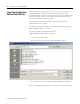
Chapter 1 Developing an RSLogix 5000 Application Creating a New Project 1. In RSLogix, open the MMCL_V200_AOI_YYYYMMDD.acd file provided in the MMCL. This application contains all Add-On Instructions. 2. Under File, select Save As. 3. Type your desired project name (for example, UserProject_yyyy_mm_dd.acd) and click Save. Configure Hardware I/O Modules All I/O modules used by the application are inserted and configured with the I/O configuration tool. 1.
Developing an RSLogix 5000 Application Import Tags with the Data Retrieval Tool CSV Files When using the AC for tag designations, you can export a.csv file, from the Data Retrieval Tool and import the data to RSLogix 5000. This import automatically creates the tags and its members, for all devices specified in Data Retrieval Tool. The .csv files are created by the Data Retrieval Tool export function and imported into RSLogix 5000.
Developing an RSLogix 5000 Application Alias I/O Descriptor 11 The Alias I/O descriptor specifies the exact hardware terminals and the particular I/O module. It is therefore, necessary to know how the I/O modules are installed and wired. Example of Tag Properties Tag Name imported from the Data Retrieval Tool CSV file I/O Address, where: _E1A_F002 = Adapter Name 1:I.0 = Slot 1:Input Module.Bit 0 IMPORTANT Do not assign the same Alias twice.
Developing an RSLogix 5000 Application The following is an example I/O Configuration with Controller Tags and Alias I/O addresses: Publication RA-UM002B-EN-P - November 2010
Developing an RSLogix 5000 Application Creating User Programs 13 The RSLogix 5000 project originates from the MMCL_V200_20100501.acd file. The following program and data folders are included in the project. User Programs are called in the Periodic Task. This is to improve overall system performance. To allow proper interaction between MMCL Add-On instruction standard functions, when multiple period tasks are used, the Period and Priority configuration for all tasks should be the same.
Developing an RSLogix 5000 Application Program Design and Application Tips • User Programs can be called by the Continuous or Period Tasks. When Periodic Tasks are used, certain rules have to be followed because the MMCL Add-On Instruction Standard Functions are originally designed for Continuous Tasks. • Setup the I/O module, or device parameters, immediately after a new module is installed. • The System Group Module, SysGrp_AOI, must be called only once in the application.
Standby E52_PG0_C1_SBY Gate 2 E52_PG2_C1_SEL Group Master E52_000_00 CtrlGrp Bus E52 Bin Feed AllRun/AllStop .1 E52_000_01 MaGrp .0 .0 .0 E52_000_02 MaGrp I/O I/O .1 Bus I/O E52_BE1_M2 MotorN/W I/O Local only operation I/O E52_BE1_M1 MotorN/F I/O Bus I/O I/O Bucket Elevator Auxiliary Drive Group Master E53_000_00 CtrlGrp Bus E53 Recirculation AllRun/AllStop Recirc E53_BC1_C1_SEL Recirculation .1 E51_000_04 MaGrp .0 .
Developing an RSLogix 5000 Application Grouping of Programs For a clear program structure, it is recommended, to specify separate programs for each Control Group. To start a new program, right-click the MainProgram and select New Routine.
Developing an RSLogix 5000 Application 17 Publication RA-UM002B-EN-P - November 2010
Developing an RSLogix 5000 Application Notes: Publication RA-UM002B-EN-P - November 2010
Chapter 2 Rules and Recommendations Add-On Instruction Interface Definition Function Name and Description Backing Tag, for example _512_BC3_D1 I/O connection from/to application Module Data Structure, for example _512_BC3_D1_C Bus connection to Parent Module All Modules access the same Global Data The Backing Tag (instance name of the Add-On Instruction) must be unique. The name of the ModuleData Tag is the same as the Backing Tag extended by "_C " (for control).
Rules and Recommendations Typical Add-On Instruction Function Call Each MMCL Add-On Instruction function has three data structures: • All direct Inputs/Outputs are specified by the Backing Tag (instance name of Add-On Instruction). • The ModuleData Tag is referenced by the Add-On Instruction, this data may be read and written by other modules/devices. It contains HMI data (Sta, Cmd, and Val) or Parameters (Par).
Rules and Recommendations Using Parameters 21 It is important to set device parameters correctly in order to avoid malfunctioning devices. After creating the tags, when importing the .csv file from the Data Retrieval Tool, you should download the default parameter values created by the Data Retrieval Tool, using the built in Tag Up-/Download tool. When you program a device, we recommend that you immediately verify the parameter settings, according to your application.
Rules and Recommendations Enable Alarming in Analog Modules To use the alarming capabilities of the AnaInp, AnaInpC and ActMod modules, you must enable each alarm individually. This can be done by either setting the tags .EMA/.EHA/.ELA/.ENA to 1 while you are programming the device, or by switching the tags dynamically from On to Off through the logic program according to the application requirements.
Chapter 3 Control Group The Control Group Module (CtrlGrp) provides the Human Machine Interface (HMI) and the main control circuit, for a group of machines, or devices that are started and stopped as an entire group. The term Group, refers to the Asset Code (AC) definition, with the assumption that one AC Group can be controlled by one CtrlGrp, but also may be controlled by several CtrlGrps. The CtrlGrp accepts commands from FactoryTalk View SE.
Control Group Group Sequence Step Controller The central part of the CtrlGrp is a seven-step controller, of which status is available to the user. The steps 0..6 shown below, represent the actual group status, in automatic mode. Status 0 is stopped, a normal start/stop sequence runs the steps from 1 through 6, one after the other, and terminates at status 0, if the group is stopped again.
Control Group 25 Step “Ready” Group has the ability to re-start, if step 4 “Ready” is active. Step Ready, is active, until Group (restart) is started again. When step Ready is active, there is a blue indication on the HMI Control- Group Popup. If the Group is restarted with the Start button, it jumps directly to step 1 “Startup”. During this re-starting situation, the Automatic Signal “EnAuto(X/Y)” is always true.
Control Group * If the group has not already started a motor, status 1 and 2, will directly pass over to status 0. Each status change, further causes an output ResetSFC, that can be used to initialize (reset) the Sequential Function Chart (SFC). The SFC then selects the actual sequence (e.g. stop sequence).
Control Group Local Operation 27 Local operation can at any time be selected, i.e. a group may be running, while certain machines within the same group, can be started and stopped locally. Automatic operation uses the control sequence described above and is transferred from the operator panel (template), by means of the group start/stop pushbuttons and monitors for mimic displays and alarming.
Control Group Enabling Automatic Operation Each Control Group CtrlGrp provides two outputs, an EnAutoStart (enable automatic start) and an EnAuto (enable automatic operation) signal, that are used for motor control and that may be switched by Machine Group Modules MaGrp. The bits are used in the application, to interlock the automatic operation of modules, such as Motors/Valves etc., that use the signals as inputs.
Control Group 29 EnAutoStart changes, in case of Restart conditions, to OFF, until CtrlGrp Sequence “Starting”, then its turn ON again. Note: Bi-directional modules as MotorR, MotorD, Valve1/2 have an EnAutoX and an EnAutoY input, for either direction.
Control Group Timing situation with Restart condition (Restart Request) The following conditions changes the Group to “Restart Request”: 1. If any of the Alarms are on “move” - Devices such as MotorN/R/D or Valve1,2. These Modules bring the alarm condition over the linked Bus -chain up to the Group. 2. If the Group is in “Starting” -state and the CtrlGrp Input .PartRun is true. 3. Or the Group is in “Running” -state and the CtrlGrp Input .AllRun changes to false. 4.
Chapter 4 Using the E3 Module Introduction The E3p_AOI module is an interface block between Network (scanner) and Motor block. Templates using the E3 module operate the same as regular MotorX module but with the add-on information from the E3 module: warning status, trip status, therm., utilized and average current. The E3p_AOI does not have a specific HMI Template. Each Motor Device with E3plus Overload Relay will call a specific HMI Template such as 03_MotorN_E3_small or 03_MotorN_E3_largel.
Using the E3 Module Principal Diagram Publication RA-UM002B-EN-P - November 2010
Using the E3 Module E3 Installation and Wiring 33 Refer to the E3 and E3 Plus Solid-State Overload Relay User Manual, publication 193-UM002, for installation and wiring details. System The E3 Overload Relays provide for data exchange over the Network of configurable Input and Output Assemblies. Inputs (Data from E3) are 8 Bytes (4Words) and Outputs (Data to E3) are 1Byte. Note: You can read more data out of the E3 then we have the possibility to reach with explicit messaging.
Using the E3 Module RSNetworx for DeviceNet Software Use the RSNetworx software to configure all E3 Overload Relays that are connected to your network. Refer to the E3 and E3 Plus Solid-State Overload Relay User Manual, publication 193-UM002, for more information This document provides additional configuration information.
Using the E3 Module E3 Operational Parameters 35 The following is a list of all parameters that must be set correctly in the E3. All others that are not in this list should be left at their default value or do not take effect with the E3p_AOI.
Using the E3 Module Parameter 24 Trip enable (default) Parameter 25 Warning enable Publication RA-UM002B-EN-P - November 2010
Using the E3 Module DeviceNet Tag Generator 37 We recommend using the RSLogix 5000 tool, DeviceNet Tag Generator, to automatically create all tags and structures in to your RSLogix 5000 project. This tool is available on the RSLogix 5000 Optional Software CD or on the DeviceNet Optional Tools CD. This tool also creates additional Routines and code in your .acd project file. The created code handles all Data exchange between the DeviceNet Scanner Data list and your Application.
Using the E3 Module Exchange Data Type To match the tags to the E3p_AOI DataInp and DataOut, you must change the Data Type of each E3 related Tag. Change the tags one by one in the Controller Tag Database or use the Tag export/import function and change the Data Type in an Excel csv file. Note: You must know which Note Number corresponds to an E3.
Using the E3 Module RSLogix 5000 Application 39 The DeviceNet Tag Generator also creates new program routines for all DeviceNet scanner data read/write commands. Application code example: IMPORTANT Always program the E3p_AOI after a Motor block. The ParentBus is always linked to the Motor local Bus, for example MotorName_C.Bus.
Using the E3 Module Notes: Publication RA-UM002B-EN-P - November 2010
Chapter 5 Inter-process Communication The IPCom module is used for inter-process communication between two programmable automation controllers. With this module, the communication to a remote controller is set up and supervising. The main function of IPCom is to distribute the bus-data. At the same time, it also transfers various numbers of user data, which can be allocated optionally and, for example, used for interlocks and user data transfer to other controllers.
Inter-process Communication Step2 Create new Controller Tags. For each remote connection we have to create a separate Tag pair. One as produced and the other as consumed type. Example: Consumed_E2 which is linked to remote controller, ConsumedCPU2 Produced_E2, which will produce and distribute this data. Produced Tags have a limit of Max Consumers. It is important to specify only the maximum number of Consumers, consuming this tag.
Inter-process Communication 43 Step3 Link the communication channel (produced/consumed) to IPCom module. If more than one remote connection to the same Controller is used, an array of IPC_Data is created and the array is extended on the required channels. In this example, we prepared a Tag with three independent channels (to the same Controller).
Inter-process Communication IPCom Bus Signal Marshaling Functions Diagram The graph below shows how the Bus is transferred through the IPCom module and the data transmitted with Produced/Consumed function.
Inter-process Communication 45 Interlock Exchange This graph shows how the predefined Interlock signals are linked. This bidirectional signal exchange is used to control (select or deselect) one MaGrp and also to bring a Group, or Device Feedback, back to the Control Group. Interlocks exchange IPCom (Master) IPCom (Slave) Master.Select Produced ->> Consumed Master.AllRunning Master.AllStopped Slave.AllRun Controller Tag Consumed <<- Produced Slave.
Inter-process Communication Communication Error Interlock In case of a Communication Error, all Devices on Slave IPCom will stop immediately. The IPCom module does not have an HMI Template (popup), to indicate this Alarm to the Operator. To bring this information to the Operator Screen, we can use a special input at CtrlGrp module, to show this information on the HMI CtrlGrp Popup. Connect CtrlGrp input .MsgDisp.n to indicate our Communication Error situation.
Chapter 6 Application Examples Example 1 – One Group with Two Selectable Feeders One Control Group with common mainstream conveyors and selectable additional feed conveyors. Material Flowsheet 1..3 Belt conveyors mainstream 4 Silo mainstream 5..
Application Examples CtrlGrp SEL En Au to P r e S el ec t . 0 AllRun MaGrp 1 1 MaGrp 2 E n A u to E n A u to MotorN P r e S el ec t . 0 Module Interlocking Diagram M1.
Application Examples 49 Ladder Program for Automatic Operation *Control Group* All devices are running in this Group M5.RdyAuto CtrlGrp.AllRun M3.RdyAuto M7.RdyAuto M5.RdyAuto SEL M7.RdyAuto SEL CtrlGrp.AllStop M3.RdyAuto CtrlGrp_AOI *Belt conveyor 1* Ctrlgrp.EnAutoStart M1.EnAutoStart Ctrlgrp.EnAuto M1.EnAuto M1_AOI ParentBus *Belt conveyor 2* Ctrlgrp.EnAutoStart CtrlGrp.Bus M2.EnAutoStart M1.RdyAuto M2.EnAuto M2_AOI ParentBus *Belt conveyor 3* Ctrlgrp.EnAutoStart CtrlGrp.
Application Examples *Machine Group 2* SEL MaGrp2.PreSelect.0 MaGrp2_AOI MasterBus SlaveBus MaGrp2.EnAutoStart M1.RdyAuto *Belt Conveyors 6* CtrlGrp.Bus Dummy.Bus M6.EnAutoStart MaGrp2.EnAuto M6.EnAuto M6_AOI ParentBus MaGrp2.EnAutoStart *Belt Conveyors 7* MaGrp2.Bus M7.EnAutoStart M6.RdyAuto M7.EnAuto M7_AOI ParentBus Publication RA-UM002B-EN-P - November 2010 MaGrp2.
Application Examples Example 2 – Two Groups with One Common Conveyor 51 Two Control Groups using a common conveyor.
Application Examples Module Interlocking Diagram Ladder Program for Automatic Operation *Control Group1* If Group selected then all Device are controlled in this Group CtrlGrp1.AllRun RF1.RdyAuto MaGrp1.Selected.0 AllRun CtrlGrp1 .Check AOI AllRun CtrlGrp2 .Check CtrlGrp1 *Control Group2* PreSelect.0 PreSelect.1 If Group selected then all Device are controlled in this Group RF2.RdyAuto MaGrp1.Selected.1 CtrlGrp2.AllRun MaGrp 1 EnAutoStart CtrlGrp2.
Application Examples 53 Publication RA-UM002B-EN-P - November 2010
Application Examples Example 3 – One Group with Two Starts A Control Group may be started in multiple steps, if the start-up sequence is interrupted by switching the Group's PartRun input ON. In this case, the CtrlGrp selects the Ready state and waits for a restart command from the operator. The diagram below shows how the output RdyAuto from Machine M2, can be used to interrupt the EnAutoStart command, by control bit B=0 and Group.PartRun=1.
Application Examples Example 4 Process Interlock 55 In this example, a Level switch (LS) will detect an Overfill situation, the Conveyer (M2) will have to stop, until the Operator starts this group again (Restart). *Process Interlock* Aux.EnStart L CtrlGrp.EnAutoStart ONS U LS.RdyOk Aux.EnStart M2.EnAutoStart M1.RdyAuto M2.EnAuto *For Restart CtrlGrp Status have to change in Ready step* LS.RdyOk CtrlGrp.PartRun M2_AOI ParentBus CtrlGrp.
Application Examples Example 5 Inter Process Communication IPCom Module Diagram: Remote CPU CtrlGrp CtrlGrp .0 .0 MaGrp1 .1 IPC2 MaGrp2 IPC1 Slave Master Device_x Device_n Device_y Device_n1 Program Code: Program from CPU1 *PLC 1 master site* Ctrlgrp.Check IPC1.Master.AllRun IPC1.Master.Select any.RdyAuto CtrlGrp.AllRun IPC1.Master.Select IPC1.Master.AllStop IPC1.Master.Select CtrlGrp.AllStop any.RdyAuto *Call IPCom module as master * IPC1 IPCom_AOI (Par.
Application Examples 57 Program from CPU2 *PLC 2 server site* any.RdyAuto any.RdyAuto IPC2.Slave.AllRunning any.RdyAuto any.RdyAuto IPC2.Slave.AllStopped *Call IPCom module as slave * Note: ParentBus is not connected IPC2 IPCom_AOI (Par.MasterModule=0) ParentBus Dummy *Transmit user data * MOV Source IPC2.UserRec.Data[0] Output_xy Dest *Control remote MaGrp * IPC2.Slave.SelectMaGrp MaGrp.PreSelect.1 MaGrp2 ParentBus IPC2.
Application Examples Notes: Publication RA-UM002B-EN-P - November 2010
Appendix A Additional Information RSLogix 5000 Workstation Options 59 Disable Duplicate Destructive Bit Detection checkbox.
Additional Information Workflow Data Retrieval Tool Publication RA-UM002B-EN-P - November 2010
Rockwell Automation Support Rockwell Automation provides technical information on the Web to assist you in using its products. At http://www.rockwellautomation.com/support/, you can find technical manuals, a knowledge base of FAQs, technical and application notes, sample code and links to software service packs, and a MySupport feature that you can customize to make the best use of these tools.