User Manual Using the Mining, Mineral, and Cement Library (MMCL) in FactoryTalk View Site Edition Applications
Important User Information Solid-state equipment has operational characteristics differing from those of electromechanical equipment. Safety Guidelines for the Application, Installation and Maintenance of Solid State Controls (publication SGI-1.1 available from your local Rockwell Automation sales office or online at http://www.rockwellautomation.com/literature/) describes some important differences between solid-state equipment and hard-wired electromechanical devices.
Table of Contents Preface Introduction . . . . . . . . . . . . . . . . . . . . . . . . . . . . . . . . . . . . . . . . . . . . . . . 5 Requirements . . . . . . . . . . . . . . . . . . . . . . . . . . . . . . . . . . . . . . . . . . . . . . 5 Before You Begin. . . . . . . . . . . . . . . . . . . . . . . . . . . . . . . . . . . . . . . . . . . 5 MMCL Deliverables . . . . . . . . . . . . . . . . . . . . . . . . . . . . . . . . . . . . . . . . . 6 Reference Documents . . . . . . . . . . . . . . . . . . . . . .
Table of Contents 4 Appendix A Display Tag Reference Publication RA-UM001B-EN-P - November 2010 Control Group . . . . . . . . . . . . . . . . . . . . . . . . . . . . . . . . . . . . . . . . . . . . 60 MotorN. . . . . . . . . . . . . . . . . . . . . . . . . . . . . . . . . . . . . . . . . . . . . . . . . . 62 MotorN_E3 . . . . . . . . . . . . . . . . . . . . . . . . . . . . . . . . . . . . . . . . . . . . . . 63 MotorR . . . . . . . . . . . . . . . . . . . . . . . . . . . . . . . . . . . . . . . . . . .
Preface Introduction Requirements This document provides a description of how to create an application with FactoryTalk View Site Edition based on the Mining, Mineral, and Cement Library (MMCL). It does not show product installation or setup of IT infrastructure. Item Requirements Software • FactoryTalk View Site Edition 5.0 or higher • RSLinx Enterprise 5.0 • FactoryTalk Services Platform 2.
Preface MMCL Deliverables Publication RA-UM001B-EN-P - November 2010 The MMCL project contains display templates for the following modules.
Preface Module Description Display Template Names ActMod Actuator Module 05_ActMod_small 05_ActMod_large 05_ActMod_param 000_Sim_ActMod PidMod PID Module 06_PidMod 06_PidMod_param 000_Sim_PidMod CtrlGrp Control Group Module 11_CtrlGrp 11_CtrlGrp_param SysGrp System Group 11_SysGrp 11_SysGrp_param IPCom Inter Process Communication Module NA Motor2N Two Speed Motor 03_Motor2N_small 03_Motor2N_large Valve3 Valve with 3 positions 03_Valve3_large 03_Valve3_small DigPulse Digital Pulse I
Preface Reference Documents • FactoryTalk View Site Edition User’s Guide, publication VIEWSE-UM006 • Integrating the Mining, Mineral, and Cement Library (MMCL) into RSLogix 5000 Applications, publication RA-RM002A-EN-P • Using the Mining, Mineral, and Cement Library (MMCL) in RSLogix 5000 Applications, publication RA-UM002B-EN-P Publication RA-UM001B-EN-P - November 2010
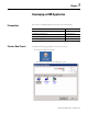
Chapter 1 Developing an HMI Application Prerequisites Create a New Project The creation of a HMI Application is based on the following files. File Source MMCLibrary (FactoryTalk View Site Edition Project) Library HMITag-[shortcut name].csv Data Retrieval Tool Alarms-[shortcut name].csv Data Retrieval Tool HMIDerivedTags-[shortcut name].csv HDRS Data Retrieval Tool Complete the following procedure to create a new project. 1. Start FactoryTalk View Studio.
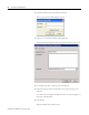
Developing an HMI Application 2. Select Site Edition (Network) and click Continue. The Log On to FactoryTalk dialog box opens. 3. Enter your User name and Password and click OK. The New/Open Site Edition (Network) Application dialog box opens. 4. On the New tab, enter a name for the overall project. 5. Select the language which corresponds to the regional setting of the computer. You will be able to translate the application into any other language at a later state of development. 6. Click Create.
Developing an HMI Application 11 7. To split the project into different areas hosting an HMI Server, right-click the CEM project and select New Area. 8. Type an area name and click OK. 9. Right-click the newly created area and select Add New Server > HMI Server. 10. Select Create a new HMI server and click Next.
Developing an HMI Application 11. Type a name and description for the new HMI server. 12. Type or browse to the computer name that will host the new server. 13. Click Finish. Data Server Setup To communicate with the different controllers on the network, a data server must be configured. For communication with ControlLogix processors, we are using RSLinx Enterprise software. A data server can be created for each area or per project. Complete the following procedure to create a new data server.
Developing an HMI Application 13 1. Right-click the newly created area and select Add New Server > Rockwell Automation Device Server (RSLinx Enterprise). The new data server is created. 2. To add a new driver, double-click Communication Setup. The Communication Setup dialog box opens. 3.
Developing an HMI Application The Add Driver Selection dialog box opens. 4. Select Ethernet and click OK. The Ethernet Properties dialog box opens. 5. Click OK to keep the default name or enter a new name and click OK. 6. Right-click the Ethernet driver and select Add Device. The Add Device Selection dialog Box opens. 7. Browse to the Ethernet device that is connected to the controller (for example, the 1756-ENBT/A) and expand it.
Developing an HMI Application 15 8. Select the revision that corresponds to your Ethernet device and click OK. TIP In the following steps you create shortcuts to the HMI tags in your controllers. 9. Browse to the controller and select it. 10. Click Add. 11. Type a shortcut name (do not use spaces) which corresponds to name defined in the Data Retrieval Tool. IMPORTANT The shortcut name must correspond to the defined name in the Data Retrieval Tool.
Developing an HMI Application Import Templates from the Library Project In this section, the display templates are loaded into the empty HMI project. Displays 1. Expand the project until the Graphics folder is expanded. 2. Right-click Display and select Add Component Into Application. 3. Browse to the Library Project and open the Gfx folder. 4. Select all the files in the folder and click Open. The display templates and sample screens are imported into your project.
Developing an HMI Application 17 Images In this section bitmap images, which are used in the display templates, are imported into the project. 1. Right-click Images and select Add Component Into Application. 2. Browse in the Library Project to the Images folder. 3. Select all the files in the folder and click Open. The images are imported into your project. Macros In this section macros, which provide Startup and Shutdown batch commands, are imported into the project. 1.
Developing an HMI Application Derived Tags In this section, a derived tag file, for heartbeat handshake with a ControlLogix controller, is imported into the project. 1. Right-click Derived Tags and select Add Component Into Application. 2. Browse in the Library Project and open the DTS folder. 3. Select the heartbeatfct.dts file and click Open. 4. The derived file is imported into your project.
Developing an HMI Application Import Tags with the Data Retrieval Tool 19 The Data Retrieval Tool can export all the required tag and alarm settings for each object used in FactoryTalk View SE. The following three files are generated for each processor: • HMITag-[shortcut name].csv • Alarms-[shortcut name].csv • HMIDerivedTags-[shortcut name].csv Where [shortcut name] is the shortcut created in the Communication Setup. 1. Under Tools select Tag Import and Export Wizard.
Developing an HMI Application 4. Browse to the .eds file for the project into which you want to import the tags and click Next. 5. Browse to the .csv files for the Tags and Alarms which you want to import and click Next. Manually Created Tags The following memory tags must be created manually in FactoryTalk View SE. These tags are used for some MMCL functionalities. To open this dialog box, select HMI Tags > Tags.
Developing an HMI Application User Accounts 21 The following five security accounts must be created in FactoryTalk View SE for the library templates: • • • • • Administrators Engineers Electricians Operators Viewers To open this dialog box, under Settings, select Runtime Security.
Developing an HMI Application To assign security codes to different accounts, press Security Accounts button and the Security window opens.
Developing an HMI Application Import the MMCL Project 23 Instead of importing the individual elements of the MMCL project one-by-one, the entire project can be imported and used as a base project. Complete the following steps to import the project. 1. Copy the MMCL_HMI_Server_V2.zip file (or appropriate version) from the MMCL CD to your hard drive. 2. Unzip the file into the working directory of FactoryTalk View SE.
Developing an HMI Application 6. Right-click the new area and select Add New Server > HMI Server. 7. Select Copy an HMI server. 8. Click Next.
Developing an HMI Application 25 9. Browse to or enter the name of the computer that hosts the existing HMI server. 10. Click Next. 11. Select MMCLibrary_v2 which was unzipped in step 2 from the MMCL CD. 12. Click Next.
Developing an HMI Application 13. Enter a name for the new server. 14. Click Finish. 15. Follow the steps in Data Server Setup on page 12 to add a new Data Server. Note: MMCL_HMI_Server_V2.zip also contains four other HMI server folders which store overview graphics for different areas/departments in Cement Industry for user reverence. They are MMC_Auxiliaries, MMC_CementMills, MMC_Kiln, and MMC_RawMaterials.
Developing an HMI Application Creating New FactoryTalk View SE Displays 27 00_Header 00_Header Display must be configured always as startup page and may not be closed at any time. This page contains Visual Basic code for supervising the communication to the controller(s). It is monitoring the HMI tag “ComERR” and popup the screen “20_ComErr”. The HMI Tag ComErr is generated by the ComErr Event which is monitoring the Heartbeat tag for communication errors.
Developing an HMI Application Communication Supervision of a Controller and FactoryTalk View SE HMI Tag Publication RA-UM001B-EN-P - November 2010
Developing an HMI Application 29 00_Footer The 00_FTUserLogon macro opens the 00_Footer display at startup. You can place a plant overview onto this display in order to jump to any sub-displays. This display is a sample display which can be modified for quick access to any location in the project. User displays The user displays are created using the library objects on the 99_RA_CEM_Library display. The displays are designed for screen resolutions of 1280x1024.
Developing an HMI Application Tag Substitution Use the following procedure to replace the standard placeholders in the modules on the following pages. 1. Drag the module group to your new display. 2. Right-click the module and select Tag Substitution. 3. Replace the following placeholders with the appropriate Asset Code (AC).
Developing an HMI Application 31 Digital Input Module To replace placeholders in the module, see Tag Substitution on page 30. When the project is running, click on the module to open the 04_DigInp display. The module is not visible when it is in normal state.
Developing an HMI Application MotorN Module To replace placeholders in the module, see Tag Substitution on page 30. When the project is running, click on the module to open the 03_MotorN_small display. If the motor is in Single start mode, the 03_MotorN_large opens. The motor symbol turns green to indicate the running state.
Developing an HMI Application 33 MotorR Module To replace placeholders in the module, see Tag Substitution on page 30. When the project is running, click on the module to open the 03_MotorR_small display. If the motor is in Single start mode, the 03_MotorR_large display opens. If necessary, you can replace the symbol assigned to the group.
Developing an HMI Application MotorD Module To replace placeholders in the module, see Tag Substitution on page 30. When the project is running, click on the module to open the 03_MotorD_small display. If the motor is in Single start mode, the 03_MotorD_large display opens. If necessary, you can replace the symbol assigned to the group. SubSys Module To replace placeholders in the module, see Tag Substitution on page 30.
Developing an HMI Application 35 Valve1, Valve2, Valve3 Module To use Valve 2 or Valve 3, choose the appropriate module. To replace placeholders in the module, see Tag Substitution on page 30. When the project is running, click on the module to open the 03_Valve1_small display. If the motor is in Single start mode, the 03_Valve1_large display opens. If needed, you can replace the symbol assigned to the group.
Developing an HMI Application ActMod Module To replace placeholders in the module, see Tag Substitution on page 30. When the project is running, click on the module to open the 05_ActMod_small display.
Developing an HMI Application 37 PID Module To replace placeholders in the module, see Tag Substitution on page 30. Click on the touch zone to open the 06_PIDMod display. You can find a description of this faceplate in the operation description of the display.
Developing an HMI Application Control Group Module Change the caption of the button from GRP to the AC Group Number of the module (the H123 placeholder, for example, E51). To replace placeholders in the module, see Tag Substitution on page 30. The display is based on the assumption that a Control Group is always named _H123_H456_H78 where H123 is the HAC Group Number, 456 is the AC Asset Unit and H78 is the AC Component (for example, E51_000_00).
Developing an HMI Application 39 System Group Module Change the caption of the button from GRP to the AC Group Number of the module (the H123 placeholder, for example, E50). To replace placeholders in the module, see Tag Substitution on page 30. The display is based on the assumption that a System Group is always named H123_H456_H78. Where H123 is the HAC Group Number, H456 is the AC Asset Unit and H78 is the AC Component (for example, E50_000_000).
Developing an HMI Application Creating Equipment There are some preconfigured pieces of equipment, which can be dragged to the user display. Each piece of equipment is composed of several objects. To replace placeholders in the equipment, see Tag Substitution on page 30. Some pieces of equipment may not require all of the substitutions listed in the procedure. For example, the belt conveyor, above, only requires that the H123 and H456 substitutions are made.
Developing an HMI Application Modifying Graphic Objects When you are using template graphics, do not modify the whole template to change the shape or size of individual objects. This distorts fonts and other objects in the graphic. Instead, only modify that object which needs to be changed. See the example below for further explanation. Selection Buttons for Machine Groups (MaGrp) There are many ways to generate selection buttons or switches. This section describes how to add template buttons.
Developing an HMI Application System Display The system display is used for diagnostic purposes and is just an example. It could be a base for creating system displays applying to the plant application.
Developing an HMI Application 43 Communication Supervision The heartbeat mechanism is used to check if the FactoryTalk View SE Data Server is still alive. The HMI tag Heartbeat reads a pulse from the ControlLogix software. The derived tag function HeartbeatFct writes the status of the Heartbeat tag to the derived tag HeartbeatRet. The ControlLogix software monitors this tag for timeouts and generates an alarm.
Developing an HMI Application Diagnostic The ControlLogix software provides a tag indication for proper Network Communication {[E50_V16]NetworkOK.0}. On Network error, the module color changes to RED. Clicking on the module opens a Network diagnostic display for this network. Clicking on the two processor modules next to DNB module in the chassis also opens two different Controller Diagnostic faceplates. One is RSLinx software-based and the other one is L_CPU_AOI instruction-based.
Developing an HMI Application Trends 45 To use the trend ActiveX in FactoryTalk View SE, the trend data must be configured in an Data Log Model in order to be visible in the displays. The following tags must be added to the Data Log Model named ‘day’.
Developing an HMI Application Alarming When the files from the Data Retrieval Tool (HMITag-[shortcut name].csv and Alarms-[shortcut name].csv) have been imported, all the necessary alarm configuration of the Tags from the Data Retrieval Tool is complete. The imported alarms use the configuration in the Alarm Setup (double-click the Alarm Setup) on the User Msgs tab.
Developing an HMI Application 47 Digital Alarms The standard configuration is defined as follows. These settings can be modified according to the project application’s requirements.
Developing an HMI Application Analog Alarm The standard configuration uses four thresholds, defined as follows. Threshold Severity Alarm Label Direction H123\H456\H78\Set\NV 1 H123-H456.H78:NA Decreasing H123\H456\H78\Set\LV 2 H123-H456.H78:LA Decreasing H123\H456\H78\Set\HV 2 H123-H456.H78:HA Increasing H123\H456\H78\Set\MV 1 H123-H456.H78:MA Increasing An alarm is not clearable until the device in alarm is back in a normal state.
Developing an HMI Application 49 Derived Tags - Alarming The last step to configure the alarm is to create a derived tag file named ‘Alarming’. One file from the HDRS Data Retrieval Tool (HMIDerivedTags-[shortcut name].csv could be used to copy and paste Derived Tag Name and Expression into this file.
Developing an HMI Application Notes: Publication RA-UM001B-EN-P - November 2010
Chapter 2 Runtime Operation Common Operations Singlestart Click the Manual/Auto button to switch between the small and large versions of the display. The large version of the display includes the Singlestart buttons. This Manual/Auto button is enabled only if the user is logged in as Electrician, Engineer, or Administrator. Singlestart mode is indicated when the button is cyan. When the Singlestart mode is terminated by the Group module, the buttons are not accessible.
Runtime Operation Acknowledge If an object has an unacknowledged alarm, that object’s Acknowledge button is blue. Clicking this button sends an ACK command to the controller and acknowledges alarms for the object or the group in the alarm function. Local Mode Clicking the Local button enables the Local mode of the object. This means that the object can be controlled at the motor by the Start and Stop buttons. The Local Mode is active when the button is white.
Runtime Operation 53 Info Function Clicking the Info button brings up another popup faceplate to enter user information for the device Value Input The value input is used for the Analog and ActMod modules. Use the arrow buttons to change the values within the range indicated. Each click changes the value by 1% of the range in either direction. You can also change the value by entering the desired number within the input field.
Runtime Operation Analog/Actuator Module Publication RA-UM001B-EN-P - November 2010
Runtime Operation 55 When the replacement value is active, the Replacement button and bar graph are orange.
Runtime Operation Manual Mode Click the MAN button to select the Manual Mode of the PID Controller. Manual Mode is preselected when the MAN button is yellow. The Controller is running in Manual Mode when the indicator above the MAN button is green. In Manual Mode, the Controlled Variable can be adjusted by using the arrow keys or entering the desired value in the input field. Click the ACC button to restore the last stored setpoint.
Runtime Operation 57 External Mode Click the EXT button to select the External Mode of the PID Controller. External Mode is preselected when the EXT button is green. The controller is running in External Mode when the indicator above the EXT button is green. In External Mode, the Setpoint Variable is controlled by an external setpoint and cannot be adjusted.
Runtime Operation E50 Example 58 Publication RA-UM001B-EN-P - November 2010
Appendix A Display Tag Reference This appendix describes the tag references in the MMCL display templates.
Display Tag Reference Control Group 52 54 22 2/CurrentUserHasCode(B) 35, 36 4/32/CurrentuserHasCode(B) 22 33 38 28 16/34/CurrentUserHasCode(D) 15/26/CurrentUserHasCode(B) 18/42/62 1/CurrentUserHasCode(B) 7/CurrentUserHasCode(B) 17/60/CurrentUserHasCode(B) 25 23 30/29 24 31 100–131 40 41 37 21 50 5/27/CurrentUserHasCode(B) Set 3, Ack #2*/#2AlmUnAckd/ CurrentUserHasCode(B) Vis If (#2\AlmUnAckd)=0) and ((#1_#2_#3_#4_C.Sta.W or #1_#2_#3_#4_C.Sta.
Display Tag Reference Commands Status Status (cont.) MSGText MSGText (cont.) 17=#1.Cmd.9 29=#1.Sta.RDY Values 108=#2\MSGText\IntlStart08 124=#2\MSGText\ImmStop00 30=#1.Sta.RUN 50=#1.Val.RT 109=#2\MSGText\IntlStart09 125=#2\MSGText\ImmStop01 31=#1.Sta.STD 51=#1.Val.INR 110=#2\MSGText\IntlStart10 126=#2\MSGText\ImmStop02 32=#1.Sta.REU 52=#2\Name 111=#2\MSGText\IntlStart11 127=#2\MSGText\ImmStop03 33=#1.Sta.OCC 54=#2\Text 112=#2\MSGText\IntlStart12 128=#2\MSGText\ImmStop04 34=#1.Sta.
Display Tag Reference MotorN 52 5/34/CurrentUserHasCode(C) 24 yellow, 25 red Alarm remark: Single Mode ON/OFF MotorN_small: Display MotorN_large MotorN_large: Display MotorN_small Vis: #1.Par.DisableSingle 54 28 29 Vis: 34 and CurrentUser HasCode(C) 2 1 30 22 26 27 Set 3, Ack #3\*/#2\AlmUnAck /CurrentUserHasCode(B) 4/33/CurrentUserHasCode(B) 31 32 Vis: [Shortcut name] Global HeavyStartup AND (NOT #1.Par. HeavyStartupIgn) AND #1.Aux.Stopped Vis: #1.Par.DisableLocal #1.Sta.IntlkOK/#1.Sta.
Display Tag Reference 63 MotorN_E3 24 yellow, 25 red 5/34/CurrentUserHasCode(C) Alarm remark: Single Mode ON/OFF MotorN_E3_small: Display MotorN_E3_large MotorN_E3_large: Display 54 52 Vis: 34 and CurrentUserHasCode (C) 28 29 2 1 22 30 26 27 31 32 Set 3, Ack #4\*/#2\AlmUnAckd/ CurrentUserHasCode(B) Vis: {Shortcut name}Global HeavyStartup 4/33/CurrentUserHasCode(B) 80 81 82 AND [NOT #1.Par.HeavyStartupIgn) AND#1.Aux.Stopped Vis: #1.Par.DisableLocal #1.Sta.IntlkOK/#1.Sta.NBIntlkOK/ #1.Sta.
Display Tag Reference Commands Status Status (cont.) 25=#1.Sta.F 33=#1.Sta.REU 26=#1.Sta.UAM 34=#1.Sta.REG 27=#1.Sta.KAM 35=#1.Sta.STU Values E3 MotorR 24 yellow, 55 25 red 5/34/CurrentUserHasCode(C) 53 Vis: 34 and CurrentUserHasCode(C) 28 29 30 26 27 31 32 6 57 7 58 1 Vis: #1.Par.DisableLocal 35 35 or 23 51 50 52 Vis: 59>0 59 AND {NOT #1.Par.HeavyStaturIgn) AND#1.
Display Tag Reference 65 In the following table, #1 = [shortcut name]_H123_H456_H78_C, #2 = H123\H456\H78, and #3 = H123/H456 Commands Status Status (cont.) Values 1=#1.Cmd.0 20=#1.Sta.RXM 28=#1.Sta.TAM 50=#1.Val.RT 3=#1.Cmd.3 21=#1.Sta.RYM 29=#1.Sta.RAM 51=#1.Val.DCX 4=#1.Cmd.4 22=#1.Sta.RM 30=#1.Sta.SAM 52=#1.Val.DCY 5=#1.Cmd.5 23=#1.Sta.WAI 31=#1.Sta.IDS 53=#2\Name 6=#1.Cmd.1 24=#1.Sta.W 32=#1.Sta.IDP 55=#2\Text 7=#1.Cmd.2 25=#1.Sta.F 33=#1.Sta.REU 56=#2\XText 26=#1.Sta.
Display Tag Reference MotorR_E3 24 yellow, 25 red 55 5/34 /CurrentUserHasCode(C) 53 Alarm remark: Single Mode ON/OFF MotorR_E3_small: Display MotoR_E3_large MotoR_E3_large: Display MotorR_E3_small Vis: #1.Par.DisableSingle 28 29 30 26 27 31 32 Vis: 34 and CurrentUserHasCode(C) 56 6 57 7 58 1 80 81 Set 3, Ack #4\* /#2\AlmUnAckd /CurrentUserHasCode(B) 4/33/CurrentUserHasCode(B) 50 51 52 Vis: 59>0 82 83 Vis: #1.Par.DisableLocal 35 35 or 23 #1.Sta.IntlkOK/#1.Sta.NBIntlkOK/ #1.Sta.
Display Tag Reference Commands Status Status (cont.) Values 6=#1.Cmd.1 24=#1.Sta.W 32=#1.Sta.IDP 55=#2\Text 7=#1.Cmd.2 25=#1.Sta.F 33=#1.Sta.REU 56=#2\XText 26=#1.Sta.UAM 34=#1.Sta.REG 57=#2\YText 27=#1.Sta.KAM 35=#1.Sta.STU 58=#2\0Text 67 E3 59=#1.Val.
Display Tag Reference MotorD 5/34 CurrentUserHasCode(C) 24 yellow, 25 red 55 53 Alarm remark: Single Mode ON/OFF MotorD_small: Display MotorD_large MotorD_large: Display MotorD_small Vis: #1.Par.DisableSingle Vis: 34 and CurrentUserHasCode(C) 56 6 28 29 57 7 30 26 58 1 27 31 32 36, 37 38, 39 40, 41 50 51 52 Vis: 59>0 59 Set 3, Ack #3\* /#2\AlmUnAckd /CurrentUserHasCode(B) 4/33/CurrentUserHasCode(B) Vis: #1.Par.DisableLocal 35 Vis: [Shortcut name] Global.HeavyStartup AND (NOT #1.Par.
Display Tag Reference Commands Status Status (cont.) Status (cont.) Values 27=#1.Sta.KAM 35=#1.Sta.STU 43=#1.Sta.ZY 57=#2\YText 28=#1.Sta.TAM 36=#1.Sta.TXAM 69 58=#2\0Text 59=#1.Val.
Display Tag Reference MotorD_E3 24 yellow, 25 red 5/34/CurretnUserHasCode(C) 55 Alarm remark: Single Mode On/Off MotorD_E3_small: Display MotorD_E3_large MotorD_E3_large: Display MotorD_E3_small Vis: #1.Par.DisableSingle Vis: 34 and CurrentUserHasCode(C) 53 28 29 30 26 27 31 32 36, 37 38, 39 40, 41 80 81 82 83 50 51 52 Vis: 59>0 59 56 6 57 7 58 1 Set 3, Ack #4\*/#2/AlmUnAckd/ CurrentUserHasCode(B) 4/33/CurrentUserHasCode(B) Vis: #1.Par.DisableLocal 35 or 23 35 #1.Sta.IntlkOK/#1.Sta.
Display Tag Reference Commands Status Status (cont.) Values E3 1=#1.Cmd.0 20=#1.Sta.RXM 32=#1.Sta.IDP 50=#1.Val.RT 80=#3.DeviceStatus.1 3=#1.Cmd.3 21=#1.Sta.RYM 33=#1.Sta.REU 51=#1.Val.DCX 81=#3.TripStatus 4=#1.Cmd.4 23=#1.Sta.WAI 34=#1.Sta.REG 52=#1.Val.DCY 82=#3.AverageCurrent 5=#1.Cmd.5 24=#1.Sta.W 35=#1.Sta.STU 53=#2\Name 83=#3.ThermUtilized 6=#1.Cmd.1 25=#1.Sta.F 36=#1.Sta.TXAM 55=#2\Text 7=#1.Cmd.2 26=#1.Sta.UAM 37=#1.Sta.TYAM 56=#2\XText 27=#1.Sta.KAM 38=#1.Sta.
Display Tag Reference SubSys 24 yellow, 25 red 5/34 /CurrentUserHasCode(C) 54 Alarm remark: Single Mode ON/OFF SubSys_small: Display SubSys_large SubSys_large: Display SubSys_small Vis: #1.Par.DisableSingle 52 28 29 Vis: 34 and CurrentUserHasCode(C) 22 2 30 26 1 27 31 32 36 37 50 Set 3, Ack #3\* /#2\ AlmUnAckd /CurrentUserHasCode(B) Vis: #1.Par.DisableLocal 35 35 or 23 51 Vis: 55>0 55 Vis:[Shortcutname] Global.HeavyStartup Vis: CurrentUserHasCode(B) AND (NOT #1.Par.
Display Tag Reference 73 Analog Enhanced 24 yellow, 25 red 54 52 Set 3, Ack #2\*/#2\AlmUnAckd/CurrentUserHasCode(B) Set 1, 21/41/CurrentUserHasCode(C) Vis: #1.Par.EnBypass or 21 56/20 and CurrentUserHasCode(C) 32 33 38 57 40/59/39 60 46/Current UserHasCode(C) 47/Current UserHasCode(C) 48/Current UserHasCode(C) 61 49/Current UserHasCode(C) Display AnaInpC_small Vis: CurrentUserHasCode(B) 41/#1.Par.
Display Tag Reference In the following table, #1 = [shortcut name]_H123_H456_H78_C, #2 = H123\H456\H78, and #3=[shortcut name]_H123_H456_H78 Commands Status (cont.) Status (cont.) Set (cont.) Values 1=#1.Cmd.0 25=#1.Sta.F 34=#3.EMA 42=#1.Set.MV 50=#1.Val.PV 3=#1.Cmd.3 26=#1.Sta.KA 35=#3.EHA 43=#1.Set.HV 51=#1.Val.PVA 27=#1.Sta.MA 36=#3.ELA 44=#1.Set.LV 52=#2\Name Status 28=#1.Sta.HA 37=#3.ENA 45=#1.Set.NV 54=#2\Text 20=#1.Sta.ESP 29=#1.Sta.LA 38=#1.Sta.ParErr 46=#1.Set.
Display Tag Reference 75 Analog 24 yellow, 25 red 54 Set 3, Ack #2\*/AlmUnAckd/CurrentUserHasCode(B) 52 32 Set 1, 21/41/CurrentUser HasCode(C) Vis: #1.Par.EnBypass or 21 33 38 41/#1.Par.
Display Tag Reference Commands Status (cont.) 22=#1.Sta.KM 31=#1.Sta.EnBypass 58=#1.Val.PVZ 23=#1.Sta.ERR 32=#1.Sta.KAM 60=#1.Val.MZ 24=#1.Sta.W 33=#1.Sta.ERRM 61=#1.Val.NZ Publication RA-UM001B-EN-P - November 2010 Status (cont.
Display Tag Reference 77 ActMod Set 3, Ack #2\*/#2\AlmUnAckd/CurrentUserHasCode(B) Set 4, 38/CurrentUserHasCode(B) 24 yellow, Vis: #1.Par.DisableLocal 54 25 red Set 1, 21/41/CurrentUserHasCode(C) Vis: #1.Par.EnBypass or 21 52 57 56/20 and CurrentUserHas Code(C) 60 40/56/101 32 33 100 39 41/#1.Par.
Display Tag Reference In the following table, #1 = [shortcut name]_H123_H456_H78_C, #2 = H123\H456\H78, and #3 = [shortcut name]_H123_H456_H78 Commands Status (cont.) Status (cont.) Set Values 1=#1.Cmd.0 24=#1.Sta.W 33=#1.Sta.ERRM 40=#1.Set.SP 50=#1.Val.PV 3=#1.Cmd.3 25=#1.Sta.F 34=#3.EMA 41=#1.Set.PVZ 51=#1.Val.PVA 4=#1.Cmd.4 26=#1.Sta.KA 35=#3.EHA 42=#1.Set.MV 52=#2\Name 27=#1.Sta.MA 36=#3.ELA 43=#1.Set.HV 54=#2\Text 28=#1.Sta.HA 37=#3.ENA 44=#1.Set.LV 56=#1.Val.
Display Tag Reference 79 PIDMod 24 yellow, 25 red 53 Set 3, Ack #2\*/#2\AlmUnAckd /CurrentUserHasCode(B) 52 26 23 60 50 51 58 62 51 50 61 58 56 57 44 43 42 Vis: CurrentUserHasCode(B) Vis: CurrentUserHasCode(C) Color: #20 Set 7, Set 40 Vis 22 and CurrentUserHasCode(B) Vis: CurrentUserHasCode(C) Val 51 Vis 21 and 33 and CurrentUserHasCode(B) Color 33 Set 40 Label 51 Val 50 Label 50 Val 58 Vis 34 and CurrentUserHasCode(B) Vis: 33 AND 21 AND CurrentUserHasCode(B) Color 34 If 40>61 Then 40 = 40 - ((60
Display Tag Reference In the following table, #1 = [shortcut name]_H123_H456_H78_C, #2 = H123\H456\H78, and #3 = AC numbers for CV. Commands Status Set Values 3=#1.Cmd.3 20=#1.Sta.E 40=#1.Set.SP 50=#1.Val.PV 4=#1.Cmd.1 21=#1.Sta.ESP 41=#1.Set.CVS 51=#1.Val.SPZ 5=#1.Cmd.0 22=#1.Sta.EAC 42=#1.Set.CP 52=#2\NamePID 6=#1.Cmd.2 23=#1.Sta.ERR 43=#1.Set.CI 53=#2\Text 7=#1.Cmd.4 24=#1.Sta.W 44=#1.Set.CD 56=#1.Val.ACC 25=#1.Sta.F 57=#1.Val.CE 26=#1.Sta.CDA 58=#1.Val.CV 27=#1.Sta.
Display Tag Reference 81 Valve1 25 yellow, 26 red 5/37/CurrentUserHasCode(C) 54 Alarm remark: Single Mode ON/OFF Valve1_small: Display Valve1_large Valve1_large: Display Valve1_small Vis: #1.Par.DisableSingle 52 31 27 Vis: 37 and CurrentUserHasCode(C) 2 Set 3, Ack #3\*/#2\AlmUnAckd/ CurrentUserHasCode(B) 1 4/36/CurrentUserHasCode(B) 28 34 35 32 33 51 Vis: #1.Par.DisableLocal 6/45/CurrentUserHasCode(C) 38 or 24 38 Vis: #1.Par.EnBypass #1.Sta.IntlkOK/#1.Sta.NBIntlkOK/ #1.Sta.IntlkbypActive Vis:#1.
Display Tag Reference Commands Status Status (cont.) 4=#1.Cmd.4 23=#1.Sta.KM 36=#1.Sta.REU 5=#1.Cmd.5 24=#1.Sta.WAI 37=#1.Sta.REG 6=#1.Cmd.6 25=#1.Sta.W 38=#1.Sta.STU 26=#1.Sta.F 39=#1.Sta.SA 27=#1.Sta.UAM 40=#1.Sta.KA 28=#1.Sta.KAM 41=#1.Sta.ZXA 29=#1.Sta.TAM 42=#1.Sta.ZYA 30=#1.Sta.RAM 43=#1.Sta.ZX 31=#1.Sta.SAM 44=#1.Sta.ZY 32=#1.Sta.ZXAM 45=#1.Sta.
Display Tag Reference 83 Valve2 28 yellow, 29 red 5/40 /CurrentUserHasCode(C) 54 Alarm remark: Single Mode ON/OFF Valve2_small: Display Valve2_large Valve2_large: Display Valve2_small Vis: #1:Par.DisableSingle 52 Vis: 40 and CurrentUserHasCode(C) 34 30 56 6 57 7 58 31 37 38 35 36 51 55 1 Set 3, Ack #3\*/#2\AlmUnAckd / CurrentUserHasCode(B) 4/39/CurrentUserHasCode(B) Vis: #1.Par.DisableLocal 8/48/CurrentUserHasCode(C) Vis: #1.Par.EnBypass #1.Sta.IntlkOK/#1.Sta.NBIntlkOK/ #1.Sta.
Display Tag Reference Commands Status Status (cont.) Status (cont.) 27=#1.Sta.WAI 39=#1.Sta.REU 52=#2\Name 28=#1.Sta.W 40=#1.Sta.REG 54=#2\Text 29=#1.Sta.F 41=#1.Sta.STU 55=#1.Val.DCX 30=#1.Sta.UAM 42=#1.Sta.SA 56=#2\XText 31=#1.Sta.KAM 43=#1.Sta.
Display Tag Reference 85 DigInp 23 yellow, 24 red 54 If 20 then local message #1 else local message #0 53 (16 characters) If 20 then local message #2 else If 25 then local message #3 else If 26 then local message #4 else If 24 then local message #5 else local message #0 Vis: 20 or 25 or 26 or 27 21 Set 1, 20/CurrentUser HasCode(C) Vis: 10 Set 3, Ack #2\*/#2\AlmUnAckd /CurrentUserHasCode(B) Vis: CurrentUserHasCode(C) Vis: CurrentUserHasCode(C) Vis: CurrentUserHasCode(B) In the following table, #1 =
Display Tag Reference DigInp2 23 yellow, 24 red 54 53 (16 characters) 28 if 20 then local message #1 else local message #0 29 If 20 then local message #2 else If 25 then local message #3 else If 26 then local message #4 else If 27 then local message #5 else local message #0 Vis: 20 or 25 or 26 or 27 Set 1, 20/Current UserHasCode(C) Vis: 10 Set 3, Ack #2\*/#2\AlmUnAckd /CurrentUserHasCode(B) Vis: CurrentUserHasCode(C) Vis: CurrentUserHasCode(B) Vis: CurrentUserHasCode(C) In the following table,
Display Tag Reference 87 DigPulse 23 yellow, 24 red 54 53 (16 characters) If 20 then local message #1 else local message #0 55 If 20 then local message #2 else If 25 then local message #3 else If 26 then local message #4 else If 27 then local message #5 else local message #0 21 Set 1, 20/CurrentUserHas Code(C) Vis: 10 30 29 26 or 27 Set 3, Ack #2\*/#2\AlmUnAckd /CurrentUserHasCode(B) 28 Vis: CurrentUserHasCode(C) Vis: CurrentUserHasCode(B) Vis: CurrentUserHasCode(C) In the following table, #1 =
Display Tag Reference Local Message Display CommErr &Set CommERR 0 Abort Publication RA-UM001B-EN-P - November 2010
Display Tag Reference 89 Value Input {#2\#3\#4\Name} {#2\#3\#4\Set\#5} #1_#2_#3_#4_C.Set.#5 #1_#2_#3_#4_C.Val.NZ #1_#2_#3_#4_C.Val.MZ If {#1_#2_#3_#4_C.Set.#5}<{#1_#2_#3_#4_C.Val.MZ} Then {#1_#2_#3_#4_C.Set.#5} = {#1_#2_#3_#4_C.Set.#5} + (({#1_#2_#3_#4_C.Val.MZ}-{#1_#2_#3_#4_C.Val.NZ})/100) Else #1_#2_#3_#4_C.Set.#5 = {#1_#2_#3_#4_C.Val.MZ} Endif If {#1_#2_#3_#4_C.Set.#5}>{#1_#2_#3_#4_C.Val.NZ} Then {#1_#2_#3_#4_C.Set.#5} = {#1_#2_#3_#4_C.Set.#5} (({#1_#2_#3_#4_C.Val.MZ}-{#1_#2_#3_#4_C.Val.
Display Tag Reference SysGrp 23 yellow, 24 red 52 Set 4, 26/CurrentUserHasCode(B) 51 CurrentUserHasCode(C)/ Display 00_System /t[E50_V16] 20 25 22 5/21/CurrentUserHasCode(B) 30 31 32 33 34 35 36 37 38 50 Set 3, Ack H123\*/#2\AlmUnAckd / CurrentUserHasCode(B) 6/CurrentUserHasCode(B) 40 41 42 Vis: CurrentUserHasCode(C) Vis: CurrentUserHasCode(B) In the following table, #1 = [shortcut name]_H123_H456_H78_C, and #2 = H123\H456\H78 Commands Status Status (cont.) Values 3=#1.Cmd.3 20=#1.Sta.
Rockwell Automation Support Rockwell Automation provides technical information on the Web to assist you in using its products. At http://www.rockwellautomation.com/support/, you can find technical manuals, a knowledge base of FAQs, technical and application notes, sample code and links to software service packs, and a MySupport feature that you can customize to make the best use of these tools.