
Owner manual

INSTALLATION
WARNING
BEFORE ATTEMPTING TO INSTALL THE MINĆ
PAK PLUS MODIFICATION KIT, DISCONNECT
AND LOCK OUT ALL SOURCES OF INCOMING
POWER TO THE CONTROLLER.
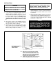
1.
Locate the area on the Regulator Module where the
Remote Operator Adapter Module is to be
mounted. Place the Module in the proper orientaĆ
tion:
the edge with 10 holes should be aligned over
the 10 pins. (Refer to Figure 2). Carefully, slowly
and gently press the Module down on the pins
until it bottoms out. Use the 2 screws to secure
it.
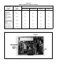
2. Based on the specific control capability of the ReĆ
mote
Operator Station chosen, select the required
wires specified in T
able 7.B, DĆ3937.
3. Draw
the wires into
the Controller through the dedi
Ć
cated
conduit. Then cut individual wires to lengths
required for connection to the kit's terminal strip.
Wire
according to Figure 3.4, D
Ć3937.
WARNING
EXCESSIVE LENGTHS OF BARE WIRE COULD
CAUSE SHORTS AND/OR GROUNDS. STRIP
MINIMAL
INSULA
TION FROM EACH WIRE.
4. Visually inspect all wiring. Check wire placement
against diagrams. Look for grounds and shorts
caused
by broken
insulation. Make sure the conduit
is
grounded.
5. Attach the blank faceplate onto the cover if not alĆ
ready
supplied. F
ollow installation instructions pro
Ć
vided
in Instruction Manual D
Ć3977 MinP
ak Plus lo
Ć
cal operator station faceplate. Be sure to attach
ground
wire to cabinet door
.
DANGER
IT IS NECESSARY TO ATTACH THE FACTORY
CONTROLLER GROUND WIRE TO THE CONĆ
TROLLER CABINET DOOR VIA THE LOCAL
OPERATORS STATION FACEPLATE. PERĆ
SONAL INJURY MAY RESULT IF THIS PRACĆ
TICE IS NOT FOLLOWED.
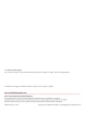
35> When remote operator buffer kit is used with
switch receiver kit auto/manual switch is conĆ
nected to 326126 and 26 (instead of 326 426 and
POT wiper) on the remote operator butter kit terĆ
minal board. The respective pins mate with NC
232 and 32 on the switch receiver kit.
36 > If NOT using an auto/manual switch for automatic
operation only jumper terminals 426 and 326.
PRINTED CIRCUIT BOARD
NOT ARRANGED IN
ORDER SHOWN.
Figure 3 - Remote Operator Adapter Kit Schematic Diagram