
Instruction Manual
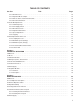

LIST OF FIGURES
Figure PageTitle
iv
Figure 1.1 - Regenerative MinPak Plus Controller and Typical Motor 1...............................
Figure 2.1 - Remote and Local Operator Control Stations 2.........................................
Figure 2.2 - Controller Chassis with Modification Kits 5.............................................
Figure 3.1 - Open Panel Minimum Mounting Distances 8...........................................
Figure 3.2 - Enclosure Mounting Minimum Distances 8............................................
Figure 3.3 - Mounting Orientations 8............................................................
Figure 3.4 - Mounting Dimensions 10.............................................................
Figure 3.5 - Chassis AĆC Ground Terminal 11......................................................
Figure 3.6 - Cover Ground Wire 11...............................................................
Figure 3.7 - Chassis Wells, Wire Routing 12.......................................................
Figure 3.8 - System Connection Diagram 13.......................................................
Figure 3.9 - Feedback Connection on Regulator Module 14.........................................
Figure 3.10 - 50ĆHz Resistor Removal 15..........................................................
Figure 3.11 - HP/Current Scaling Pins 16..........................................................
Figure 4.1 - Inspection Areas in Cover, Chassis 17.................................................
Figure 4.2 - Local Faceplate Connectors 17.......................................................
Figure 4.3 - Testing Remote Module 18...........................................................
Figure 4.4 - Testing Tachometer Feedback 18......................................................
Figure 4.5 - Field Supply in Controller 19..........................................................
Figure 4.6 - Terminals A1, A2 on 1TB 20..........................................................
Figure 4.7 - Regulator Module Pots 20............................................................
Figure 5Ć1 - Super RPMt Motor (typical) 23........................................................
Figure 5.2 - Full Wave Regenerative Bridge Configuration 24........................................
Figure 5.3 - Power Cube 24.....................................................................
Figure 6.1 - Pin Alignment 25....................................................................
Figure 6.2 - Local Faceplate with All Options 27....................................................
Figure 6.3 - Remote Adapter Kit 28...............................................................
Figure 6.4 - Dynamic Braking Kit 28..............................................................
Figure 6.5 - D.B. Resistor in Chassis 29...........................................................
Figure 6.6 - Connecting Dynamic Brake 29........................................................
Figure 6.7 - Voltage/Tachometer Follower 30......................................................
Figure 6.8 - Jumper J1 30.......................................................................
Figure 6.9 - Instrument Interface Kit 31............................................................
Figure 6.10 - Jumper J1, mA Pins 31.............................................................
Figure 6.11 - Field Supply Kit 32.................................................................
Figure 6.12 - Connecting Field Supply 32.........................................................
Figure 6.13 - Auxiliary M Contactor Kit 32.........................................................
Figure 6.14 - External Wiring, Auxiliary M 33.......................................................
Figure 6.15 - Test Meter 33......................................................................
Figure 6.16 - Master Isolated Reference Receiver Kit 34.............................................
Figure 6.17 - Jumpers J1 and J2 on Switch Receiver Module 34.....................................