
Instruction Manual

42
8. Drive motor
does not
run with M
contactor
picked up
and SPEED
pot properly
operating.
(Continued )
Regulator Module susĆ
pected because no output
reading at A1, A2.
V Test the Regulator Module for firing pulses as described below.
V Turn the POWER ON/OFF circuit breaker to OFF. Open the main disconnect.
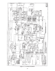
V Locate the 50f capacitor at R27Ć43 and put the voltmeter (-) lead to R27.
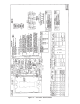
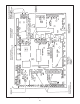
V Locate the four diodes on the Gate Coupling board near the words Gate
Coupling Card." Connect the (+) meter lead to the anode ➀ of the leftĆmost
diode (D1). Put the voltmeter on a low aĆc volt scale.
V Restore aĆc power to the controller. Put FORWARD/REVERSE switch in
REVERSE.
V Place the START/STOP switch in the START position.
V Turn the SPEED pot up to about 5.
V The reading on the VOM should be about -0.7 VAC.
V Turn the START/STOP switch to STOP and remove aĆc power.
V Repeat this test with (+) meter lead on the next diode to the right (D2).
V Repeat the test with FORWARD/REVERSE in the FORWARD position and the
(+) meter lead on each of the two rightĆmost diodes (D3 and D4).
V If any of the four readings cannot be obtained, replace the Regulator Module.
Power Cubes suspected
because no output readĆ
ingatA1,A2.
V Establish that the Power Cubes are receiving pulse inputs at the connector
on the Regulator Module. (Refer to the 2nd item just above, Regulator
Module suspected.)
V If the Power Cubes are receiving pulses yet there is no reading across A1
and A2, determine that the main contacts on the M contactor are closing.
V In order to check the contacts, replace the drive motor with a light bulb on
the armature wiring at 1TB. (On 230 VAC controllers use two light bulbs in
series.)
V If the light does not light, replace the Power Cubes.
9. Drive motor
does not
run with M
contactor
picked up
and SPEED
pot properĆ
ly operatĆ
ing.
(Use this
procedure
only if conĆ
troller has
optional
Test Meter
Adapter
Kit.)
No gate firing pulses. V Turn off power to the controller at the POWER ON/OFF circuit breaker and
the main disconnect.
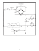
V Connect a voltĆohmmeter lead to test pin 356 on the Test Meter Module.
V Connect the second lead to test pin 817. Put the FORWARD/REVERSE
switch in the REVERSE position.
V Restore power to the controller.
V Place the START/STOP switch in the START position.
V On the VOM's +10 VDC scale, an increase of approximately +1 VDC should
be noted.
V Turn off power to the controller.
V Reconnect the VOM to test pins 356 and 816. Put the FORWARD/REVERSE
switch in the FORWARD position.
V Put the START/STOP switch in the START position.
V On the VOM's +10 VDC scale, an increase of approximately +1 VDC should
be noted.
V If voltage readings increase, the Power Cubes are receiving pulses to the
SCRs.
V Make a last check of wiring to the Power Cubes.
V If wiring is correct, replace the Power Cubes.
10. Motor runs
but current
peaks too
high.
One phase not firing. V Perform the procedure for Symptom 8, Regulator Module suspected
because no output reading at A1, A2. If all pulses are present, one or more
Power Cubes are faulty.
➀The anodes are the leads nearest the pulse transformers (also, the leads the l.D. white circle.)
!
!