
Instruction Manual

25
The Regulator Module provides the following basic funcĆ
tions:
D Full fourĆquadrant operation.
D Major loop armature voltage regulation or speed
(tachometer) regulation
D Linear reference timing for controlled acceleration
and deceleration
D Current minor loop regulator
D Thyristor gate driver circuits
D Isolated armature voltage feedback
D Rectifier and scaling resistors for isolated current
transformer inputs to provide current feedback
D Start, stop, jog sequencing
D PowerĆup and powerĆdown sequencing
In addition the Regulator Module allows the use of a variĆ
ety of options that extend the capability of the basic conĆ
troller. (Refer to Paragraph 6.0.)
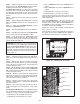
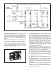
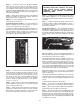
5.7.2 Description ĊThe Regulator Module is a printed
circuit board which occupies approximately half of the
Regenerative MinPak Plus controller's Chassis. Directly
behind it there is an isolation transformer which supĆ
plies isolated, lowĆvoltage aĆc power to the Regulator
Module power supplies.
All electrical connections to the Regulator Module are
made with tinĆplated pin connectors. The input/output
arrangement of these pins is intended to physically isoĆ
late the different circuits, thereby minimizing electrical
noise coupling.
All optional external voltage signals which may contain
electricalnoise are fed through filtering and isolation cirĆ
cuits prior to entering the Regulator Module. Thus, reliĆ
able operation is assured even in a noiseĆpolluted inĆ
dustrial environment.
A LargeĆScale Integrated Circuit (LSI) is incorporated
into the Regulator Module. It drastically reduces the
number of active devices, thereby producing excellent
response characteristics and an exceptionally high reliĆ
ability factor.
Physically the Module has identifications and locations
printed in highĆvisibility white paint. These callouts help
users identify potentiometers, resistors, and areas
where optional Kits are installed.
TheModule and all optional Kits have a special covering
to protect the printed circuits from conductive elements
such as moisture and dust.
Section 6
MODIFICATION KITS
6.0 General Ċ A number of optional features in the form
of Modification Kits are offered with the Regenerative
MinPak Plus controller. Each of these Kits extends the
control of the unit and tailors its operation to specific apĆ
plication needs.
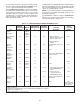
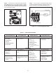
This Section describes the procedures that must be folĆ
lowedto install the Kits. Refer to Table6.A for an informaĆ
tional listing.
DANGER
INSTALLATION OF MODIFICATION KITS IS TO
BE DONE ONLY AFTER AĆC LINE VOLTAGE IS
DISCONNECTED AND LOCKED OUT AT THE
MAIN DISCONNECT SWITCH. DO NOT INSTALL
KITS WHEN POWER IS APPLIED TO THE REĆ
GENERATIVE MINPAK PLUS CONTROLLER.
SERIOUS PERSONAL INJURY AND EQUIPĆ
MENT DAMAGE COULD RESULT.
CAUTION: Installation of the Modification Kits
should be performed only by qualified electrical
maintenance personnel familiar with the design
and operation of this equipment. Damage could reĆ
sult thru unfamiliarity.
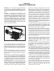
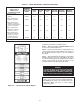
Many of the Modification Kits are designed to make elecĆ
trical connection with the Regulator Module by means of
pinĆtype connectors. These slide up through matching
holes in the Modules that form part of the Kit. (Refer to
Figure 6.1.)
Pins must be parallel
Figure 6.1 - Pin Alignment
A common installation problem is caused by bent, broĆ
ken or incorrectly placed pins. Since improper operation
results, care must be taken. Exact alignment is critical.
Visually check that only one pin extends to the top of
each slot once the connection is made.
Many of the Modification Kits require the removal of one
or more jumpers from the Regulator Module. In such
cases carefully clip the leads on both sides of each jumpĆ
er and discard it. Use a sharp pair of dykes (diagonal cutĆ
ters) to assure a quick, clean cut. Do not twist the tool,
since damage may result.