! ! ! ! # " $ # ! ! ! " ! " $ $
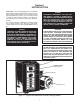
Section 1 INTRODUCTION 1.0 General Ċ This manual familiarizes the user with the Reliance Electric Regenerative MinPakt Plus DĆC VKSR drive controller. (Refer to Figure 1.1 ) It describes assemĆ bly and installation procedures, gives a general overview of operation, and contains information on troubleshootĆ ing. maintenance, the ordering of spare parts, and speciĆ fications.
" Ċ The Regenerative MinPak Plus DĆC VKS drive controller may be applied to singleĆphase dĆc drive applications with ratings within the following ranges: D From 1/4 to 3/4 hp with a 115 VAC, 50/60 Hz input voltage D From 1/2 to 5 hp with 230 VAC, 50/60 Hz input voltage D RUN/JOG selector switch D FORWARD/REVERSE selector switch D START/STOP selector switch There are two basic configurations that may be selected: D Station mounted on controller Chassis Cover (
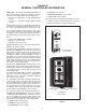
! # # ! Ċ When the Station is mounted loĆ cally on the Cover, users may select from five standard Faceplates in order to configure a controller to a specific drive application Refer to Table 6.B which is an inclusive listing of Faceplate types, Model Numbers and functions. Assuming the Cover is properly installed, the Faceplate design maintains the NEMA Type 4/12 rating. !# # # ! " Ċ Some applications may reĆ quire that the Operator's Control Station be remotely loĆ cated.
D Order a Remote Operator Adapter Kit, Model 14C220. (This unit provides a connection point for the Remote Station .) D Specify a Reliance Electric Remote Operator ConĆ trol Station. Connect it to the controller. singleĆphase power source having a frequency range from 48 to 62 Hz. However, for optimum 50ĆHz operation, it is recommended that two resistors be removed from the Regulator Module. (Complete details are given at Paragraph 3.9.
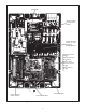
Field Supply Dynamic Braking mounts behind Bracket Auxiliary M Module mounts on center of Auxiliary Mounting Bracket Voltage/Tachometer Follower or Instrument Interface/ Preset Speed or Master Isolated Reference Receiver Module or Dancer Follower Module Remote Operator Adapter Module Test Meter Adapter Tachometer Feedback 5
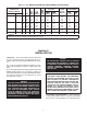
Table 2.C - SPECIFICATIONS AĆC Line Input Voltage 115/230 VAC (nominal) singleĆphase only Armature Circuit Overload Capacity 150% of armature current rating for 1 minute (max.
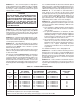
Table 2.D - DĆC MOTOR/CONTROLLER/TRANSFORMER SPECIFICATIONS CONTROLLER MODEL NUMBERS ENCLOSED CHASSIS 14C30 14C40 HP 1/4 1/3 1/2 3/4 AĆC A C DĆC D C AMPS ARM. VAC (RMS) (VOLTS) 115 ă3.5 ă90 115 ă5.2 ă90 115 ă7.0 ă90 115 10.5 ă90 DĆC ARM. AMPS (avg.) ă2.5 ă3.7 ă5.0 ă7.5 OPTIONAL DĆC AMP. FIELD MAX MAX. VOLTS (optional) 100 100 100 100 3.0 3.0 3.0 3.0 TRANSFORMER POWER MAXIMUM FULL SUPPLY kVA LOAD CAPACITY Per Phase kVA ➁ 1000 40 ă0.75 1000 40 ă0.75 1000 40 1.0 1000 40 1.
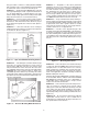
Guideline 5 Ċ Regardless of the above placement guidelines, the user is responsible for providing ambient temperatures that meet the controller's specifications. For units mounted on an open panel or wall and using the standard Cover, this range is 0° to 40°C (32° to 131°F). For units mounted in a ChassisĆonly configuraĆ tion in a larger cabinet, this range is 0° to 55°C (32° to 131°F). Relative humidity must be kept between 5 and 95% without condensation if a Cover is not used.
Guideline 11 Ċ The controller requires a singleĆphase power supply that provides either 115 VAC or 230 VAC at 50/60 Hz. If correct voltage is not available, it will be necessary to install a transformer between the power supply and the controller. It is recommended that the disconnect switch be placed within easy reach of operating and maintenance personĆ nel. Do not place it inside a surrounding enclosure since cabinet doors may be locked. (Consult your local codes.
Use a 1Ćinch copper braid or an 8 gauge wire and conĆ nect with the plant (central) ground. The motor frame should also be grounded. In many cases it is adequate to use a screw in the conduit box near the motor . Scrape paint around holes to assure grounding. Guideline 19 Ċ A thermostat is used to guard against motor overload protection. It is essential to properly conĆ nect the motor thermostat in series with the Operator's Control Station STOP selector switch at connections 32 and 132.
Since the green wire is fixed by the user on a Faceplate bolt, the installation should be performed when the FaceĆ plate is fitted. Full details are given at Paragraph 6.1 for the Local Station and Paragraph 6.2 for the Remote. Earth ground is defined as the central ground for all elecĆ trical and aĆc power within a facility. Frequently earth ground may also be the plant, magnetics, equipment, electrical, circuit, neutral or reference ground, dependĆ ing on the nomenclature used at a facility. 3.
1/2"-14 thread WARNING DO NOT ALLOW CONDUCTORS TO GROUND ON THE CHASSIS OR CONDUITS. CHECK INĆ TEGRITY OF ALL WIRE INSULATION BEFORE DRAWING. REMOVE ONLY ENOUGH INSULAĆ TION TO MAKE A FIRM TERMINAL CONNECĆ TION. PERSONAL INJURY COULD RESULT IF A BARE WIRE TOUCHES THE CHASSIS. 3/4"-14 thread 3/4"-14 thread Tach input wires DĆc output conductors AĆc output conductors Field Supply wiring should also be performed now. It is standard on 2, 3 and 5 hp controllers and optional on lower ratings.
13
Take these two figures and relate them to Table 3.B. Read across to the right column, where the 100% voltage figĆ ure is indicated. Place the jumper on the Module's pin that corresponds to this figure.
Remove resistor Remove resistor Figure 3.10 - 50ĆHz Resistor Removal The general requirements for an isolation transformer are: D SingleĆphase D 3Ć8% impedance D Nonregulated D Sinusoidal output D 50/60 Hz, as required D 150% overload for 1 minute (max.) Table 3.C - RELIANCE ELECTRIC ISOLATION TRANSFORMERS HP kVA 1/4-1/3 0.75 1/4-1/3 0.75 Refer also to Table 2.D for specific information on transĆ former sizing requirements. In the Transformer column at the right.
Step 3 Ċ On the Regulator Module, locate the scaling pins. (Refer to Figure 3.11.) Near them, locate the black pigĆtail type jumper. Do not move it if it is connected to the proper pair of pins. If it must be reconnected, carefully lift it straight up and off the pins. Slide the connector straight down over the proper set of pins. Table 3.D - HORSEPOWER CALIBRATION MOTOR HP 115 VAC 230 VAC 1/4 1/3 1/2 3/4 Ċ Ċ Ċ 1/2 3/4 1 1Ć1/2 2 3 5 MOTOR CURRENT/ PIN CONNECTIONS ă2.5A ă3.7A ăĂă5A ă7.
1. Incoming aĆc: conductor identifications; possible grounds; Chassis ground; firm connections. 2. Outgoing dĆc: same as 1, above. 3. Incoming tachometer: twisted wire routĆ ing; +/Ċ connections at both ends; firmly seated Module; possible shorts at conĆ nector strip. 4. Cover: standard ground wire connected? 5. Kits: firmly seated Module; one pin thru each collar; firm properly routed wiring at connector strip; possible shorts. 6. Field Kit: completed wiring from drive's F1/F2; wiring to 51/52. 7.
If a Remote Station is used. a series of wires will connect to individual terminals on a strip mounted on the Remote Operator Interface Module. (This Module is mounted on the Regulator Module. Refer to Figure 4.1.) Determine that all wires are firmly seated in the terminal strip. Make sure all wires are connected. 4.2.2 50ĆHz Resistors Ċ Although the Regenerative MinPak Plus operates without modification with a 50ĆHz frequency input, there are performance advantages if two resistors are removed.
the unit. Since not all controllers have a Field Supply. it must be determined if there is one before deciding whether or not the check must be made. The following controllers have a Field Supply: D All controllers designed for 2 thru 5 hp drives. D All controllers which are optionally fitted with a Field Supply Kit. (These kits may be used only if the dĆc motor has a wound field.) Step 1 Ċ Attach one lead from the ohmmeter to the moĆ tor frame to make a simple resistance check.
Step 5 Ċ When the voltage across F1 and F2 is at the proper level, put the POWER ON/OFF circuit breaker in the OFF position and close the Chassis Cover. D Rate 1 (FORWARD acceleration, REVERSE decelĆ eration) D Rate 2 (REVERSE acceleration. FORWARD decelĆ eration) D Current limit #1 (+) (factory set at 150%) D Current limit #2 (-) (factory set at 150%) 4.3.3 Drive Motor Check Ċ It is necessary to determine if the drive motor is rotating in the direction required by the application.
4.4.2 Maximum Speed (Voltage) Ċ The Maximum Speed potentiometer on the Regulator Module has been factory preset for 50% of a typical motor base speed of about 1750 rpm. By means of adjustment, the maximum speed may be raised to suit the application. The result is the highest speed that can be set by the operator on the SPEED dial. The control range is 50Ć100% of rated speed. Step 1 Ċ Test the SPEED potentiometer to assure that it is operating properly.
If the 10 setting on the SPEED dial is lower than the deĆ sired speed, increase the setting on the Maximum Speed potentiometer to the necessary speed by turning the poĆ tentiometer CW. 4.4.4 Acceleration/Deceleration Rates Ċ The RATE 1 and RATE 2 potentiometers on the Regulator Module are provided to adjust FORWARD and REVERSE acceleraĆ tion rates, respectively. RATE 1 also controls the decelĆ eration rate when in the REVERSE mode, and RATE 2 controls the deceleration rate when in the FORWARD mode.
Section 5 THEORY OF OPERATION 5.0 General Ċ This Section gives a generalized theory oaf operation far the Regenerative MinPak Plus controller It covers internal components and their functions It also explains the relationship oaf the drive motor and the conĆ troller. the other is connected to provide power in the reverse direction. (Refer to Figure 5.2 where it is shown in scheĆ matic form.
CURRENT FEEDBACK TO REGULATOR POWER UNIT #2 POWER UNIT #1 CIRCUIT BREAKER L1 L2 181 182 1CB 2CB MOTOR ARMATURE Figure 5.2 - Full Wave Regenerative Bridge Configuration 5.4 Power Circuit Malfunctions Ċ The power circuit Is protected against malfunctions. The peak overload conditions which may be caused by a mechanical jamĆ ming of the motor shaft are guarded against by the curĆ rent limit function and the POWER ON/OFF circuit breaker. 5.
The Regulator Module provides the following basic funcĆ tions: D Full fourĆquadrant operation.
In cases where the Kit is secured by a mounting screw, be sure to tighten it firmly but do not overtighten. ExcesĆ sive force can strip the threads in the cast base. The Faceplates are supplied with a bag of eight hex keps nuts. The standard hex nut is used to secure the ground wire. No other equipment nor any other Reliance Electric options are required with this option. 6.
Table 6.
Step 4 Ċ Locate the area on the Regulator Module where the two connectors will connect. (Refer to Figure 4.2 or 7.6.) Note there are two sets of pins. Mate the conĆ nector with the red wire in the end position connecting to the pin marked 32 (RED). Mate the second connector with the green wire in the end position connecting to the pin marked 28 (GRN). WARNING WARNING EXCESSIVE LENGTHS OF BARE WIRE COULD CAUSE SHORTS AND/OR GROUNDS. STRIP MINIMAL INSULATION FROM EACH WIRE.
Step 5 Ċ It is necessary to connect both leads to the M Contactor. Figure 6.6 shows the contactor and the elecĆ trical connections for the Dynamic Braking resistor. Step 4 Ċ Locate the area of the Chassis where the DyĆ namic Braking resistor is to be placed. (Refer to Figure 6.5 ) Using the two screws included in the Kit, mount the resistor onto the Chassis. Place the longer lead pointing to he nearer Chassis edge. longer wire first'' row D.B. M contactor Figure 6.5 - D.B.
Step 6 Ċ Replace the Circuit Breaker bracket and reconĆ nect the leads disconnected in Step 3. Step 3 Ċ Connect the wires from the tachometer to the terminal strip on the Module. Plus (+) is on the left, minus (-) on the right. Do not strip more than 1/8 inch (3mm) of insulation off since shorts occur at exposed points. Maintain the twisted character as long as possible. 6.
Step 1 Ċ Orient the Module over the dedicated area marked REFERENCE on the Regulator Module. just over the 5 pins. (Refer to Figure 7.6.) Lower it so that the pins pass through the guides on the Module. Use the screw to secure it. Step 2 Ċ Connect the external reference signal wires to the terminal strip on the Module. Plus (+) on the left, miĆ nus (-) on the right. Do not strip more than 1/8 inch (3 mm) of insulation off since shorts could occur at exposed points.
Ċ Make the same assumption as in Paragraph 6.5.1, Step 2. Ċ Connect the black pigĆtail jumper on the InterĆ face Module to the 50 mA pin. (Refer to Figure 6.10.) Ċ Locate the Auto Minimum Speed potentiomeĆ ter on the Interface Module. Turn it CW to the third dot which represents a oneĆthird turn. 51 52 To F1, F2 on motor 2TB Ċ Place the controller in the AUTO mode, if so equipped Locate the Auto Maximum Speed potentiomeĆ ter. Adjust it to obtain the desired preset speed.
41 43 42 41 NO NC COM 43 CAUTION: Under no circumstances should the probes of a meter be connected directly to the pins on the Regulator Module. Permanent damage to the solid state components can occur. COM 42 The Kit contains a Module and a mounting screw. Except for the voltmeter, no other equipment is necessary. The meter should be a multimeter having a sensitivity of 20,000 ohms per volt minimum. (Simpson Model 260, Triplett Model 630, or equivalents are acceptable.) Figure 6.
The Operator Control Station AUTO/MANUAL selector switch is used to obtain local control or master reference control of the individual drive. When the selector switch is placed in the AUTO mode, the individual drive SPEED potentiometer automatically is converted into a draw pot adjustment for precise trim control between drives. The only adjustment requirement is a zero set adjustment on the Reference Receiver Module.
Step 5 Ċ Using a twisted pair, connect the external refĆ erence wires (wires 1 and 2) from the external Master Isolated Reference Transmitter to the terminal block on the Reference Receiver Module in the controller cabiĆ net. Connect wire 1 to terminal 1 and wire 2 to termiĆ nal 2. selector switch must be used on the Local or Remote OpĆ erator Control Station. (Refer to Table 2.B.) In the MANUĆ AL position, the drive responds to the SPEED potentiomĆ eter setting.
Step 4 Ċ Using three twisted wires, connect the user supplied 5 K ohm Dancer potentiometer to the terminal strip of the Dancer Follower Module. The speed inĆ crease side of the potentiometer connects to terminal 556 and the speed decrease side connects to terminal 571. The potentiometer wiper is connected to terminal 919. Turn the GAIN potentiometer of the Dancer Follower Module fully counterclockwise for minimum Dancer poĆ tentiometer response.
D Check the field windings for open or short condiĆ tions. D Check continuity through the armature and brushes. Use the A1 and A2 wires at the controller as test points. DANGER CONTROLLER EQUIPMENT IS AT LINE VOLTĆ AGE WHEN AĆC POWER IS CONNECTED TO THE POWER UNIT IN THE REGENERATIVE MINĆ PAK PLUS CONTROLLER. THUS AĆC POWER MUST BE REMOVED FROM THE UNIT BEFORE IT IS SAFE TO TOUCH THE INTERNAL PARTS OF THE REGENERATIVE MINPAK PLUS. PERĆ SONAL INJURY MAY RESULT UNLESS POWER IS REMOVED. 7.
Ċ In order to aid with the troubleshooting process, various schematics and diaĆ grams are included here. Note that these drawings are the latest revisions as of the date of publication of this manual. The manufacturer cannot guarantee that subseĆ quent changes will not occur; although if any do, they should be minor. In cases of doubt, contact your local Reliance Electric Sales Office or Distributor D Figure 7.3 which is a schematic for the controller. D Figure 7.
SYMPTOM PROBABLE CAUSE 1. POWER ON/OFF circuit breaker on controller trips when power is Applied. Incorrect wiring connecĆ tions to controller, from controller to motor. in moĆ tor. RECOMMENDED PROCEDURES DANGER IF CIRCUIT BREAKER HAS TRIPPED, USER MUST REMOVE THE COVĆ ER FROM THE DRIVE AND DETERMINE IF A FIELD SUPPLY KIT IS PRESENT. (SEE FIGURE 4.5.) IF FIELD SUPPLY KIT IS PRESENT, THE FIELD SUPPLY KIT AND ITS WIRING MUST BE INSPECTED FOR DAMĆ AGE.
3. Remote or Local OperĆ ator Control Station functions not operatĆ ing. 4. Controller's M contactor not picking up when START switch i h is i pressed (closed). Malfunctioning switches. V Check START/STOP switch, ! remove aĆc line power at main disconnect. V Connect ohmmeter to wire 32 (red) pin on the switch. (Note numbers here refer to numbers noted on Remote Station wiring diagram on Figure 3.8.
SYMPTOM 6. Drive motor does not run, but M contactor and CR pull up. PROBABLE CAUSE No input signal from SPEED pot on Control Station, local or remote. V If the controller does not have an optional AUTO/MANUAL switch, inspect the Regulator Module to determine that jumper J4 is in place. (The jumper is removed when the AUTO/MANUAL switch is installed.) V Check the SPEED pot on the Control Station or Faceplate. First place the POWER ON/OFF circuit breaker in the OFF position.
8. Drive motor Regulator Module susĆ does not pected because no output run with M reading at A1, A2. contactor picked up and SPEED pot properly operating. (Continued ) V V V V V V V V V V V V 9. Drive motor does not run with M contactor picked up and SPEED pot properĆ ly operatĆ ing. Test the Regulator Module for firing pulses as described below. Turn the POWER ON/OFF circuit breaker to OFF. Open the main disconnect.
43
44
45
46
Control transformer secondary winding 24 VAC DĆc circuit breaker aux. approx.
48
Section 8 REPLACEMENT PARTS 8.0 General Ċ Users should consider maintaining a stock of spare parts. Table 8.A lists the more common parts along with part numbers and quantities actually used in the controller. Table 8.
TABLE OF CONTENTS Sec./Par. Title Page 1.0 General . . . . . . . . . . . . . . . . . . . . . . . . . . . . . . . . . . . . . . . . . . . . . . . . . . . . . . . . . . . . . . . . . . . . . . . . . . . . . . . . . .
TABLE OF CONTENTS Sec./Par. Title Page 4.2.2 50ĆHz Resistors . . . . . . . . . . . . . . . . . . . . . . . . . . . . . . . . . . . . . . . . . . . . . . . . . . . . . . . . . . . . . . . . . . . . . 18 4.2.3 Regulation Mode Jumper . . . . . . . . . . . . . . . . . . . . . . . . . . . . . . . . . . . . . . . . . . . . . . . . . . . . . . . . . . . . . 18 4.2.4 Remote Station, Tachometer Grounds . . . . . . . . . . . . . . . . . . . . . . . . . . . . . . . . . . . . . . . . . . . . . . . . . . 18 4.
TABLE OF CONTENTS Sec./Par. Title Page 6.7 Auxiliary M Contacts . . . . . . . . . . . . . . . . . . . . . . . . . . . . . . . . . . . . . . . . . . . . . . . . . . . . . . . . . . . . . . . . . . . . . . . 32 6.8 Test Meter Adapter . . . . . . . . . . . . . . . . . . . . . . . . . . . . . . . . . . . . . . . . . . . . . . . . . . . . . . . . . . . . . . . . . . . . . . . . 33 6.9 Master Isolated Reference Receiver . . . . . . . . . . . . . . . . . . . . . . . . . . . . . . . . . . . . . . . . . . . .
LIST OF FIGURES Figure Title Page Figure 1.1 - Regenerative MinPak Plus Controller and Typical Motor . . . . . . . . . . . . . . . . . . . . . . . . . . . . . . . 1 Figure 2.1 - Remote and Local Operator Control Stations . . . . . . . . . . . . . . . . . . . . . . . . . . . . . . . . . . . . . . . . . 2 Figure 2.2 - Controller Chassis with Modification Kits . . . . . . . . . . . . . . . . . . . . . . . . . . . . . . . . . . . . . . . . . . . . . 5 Figure 3.
LIST OF FIGURES Figure Title Page Figure 6.18 - Jumper J1 on Reference Receiver Module . . . . . . . . . . . . . . . . . . . . . . . . . . . . . . . . . . . . . . . . . . 35 Figure 6.19 - Dancer Follower Module . . . . . . . . . . . . . . . . . . . . . . . . . . . . . . . . . . . . . . . . . . . . . . . . . . . . . . . . . 35 Figure 6.20 - Jumpers J1, J2 and Resistor (R6) . . . . . . . . . . . . . . . . . . . . . . . . . . . . . . . . . . . . . . . . . . . . . . . . . 36 Figure 7.
LIST OF TABLES Table Title Page Table 2.A - REGENERATIVE MINPAK PLUS FEATURES SUMMARY . . . . . . . . . . . . . . . . . . . . . . . . . . . . . . . . 3 Table 2.B - REMOTE OPERATOR CONTROL STATIONS . . . . . . . . . . . . . . . . . . . . . . . . . . . . . . . . . . . . . . . . . 4 Table 2.C - SPECIFICATIONS . . . . . . . . . . . . . . . . . . . . . . . . . . . . . . . . . . . . . . . . . . . . . . . . . . . . . . . . . . . . . . . . . 6 Table 2.D - DĆC MOTOR/CONTROLLER/TRANSFORMER SPECIFICATIONS . .
U.S. Drives Technical Support Tel: (1) 262.512.8176, Fax: (1) 262.512.2222, Email: support@drives.ra.rockwell.com, Online: www.ab.com/support/abdrives Trademarks not belonging to Rockwell Automation are property of their respective companies. Publication D-3899-1 – December 1991 Copyright © 1991 Rockwell Automation, Inc. All Rights Reserved. Printed in USA.