$ $# !$ " ! & !$ $ $" " Receive and Accept the Shipment . . . . . . . . . . . . . . . . . . . . . . . . . . . . . . . . . . . . . . . . . . . . . . . . . . . . . 1:1 Store the Controller . . . . . . . . . . . . . . . . . . . . . . . . . . . . . . . . . . . . . . . . . . . . . . . . . . . . . . . . . . . . . . . . . . 1:1 File a Return Request . . . . . . . . . . . . . . . . . . . . . . . . . . . . . . . . . . . . . . . . . . . . . . . . . . . . . .
5: Troubleshooting General . . . . . . . . . . . . . . . . . . . . . . . . . . . . . . . . . . . . . . . . . . . . . . . . . . . . . . . . . . . . . . . . . . . . . . . . . . . . Wiring Errors . . . . . . . . . . . . . . . . . . . . . . . . . . . . . . . . . . . . . . . . . . . . . . . . . . . . . . . . . . . . . . . . . . . . . . . AĆC Line and Power Input . . . . . . . . . . . . . . . . . . . . . . . . . . . . . . . . . . . . . . . . . . . . . . . . . . . . . . . . . . . . DĆC Motor . . . . . . . . . . .
Figure 5Ć4. Figure 5Ć5. Figure 5Ć6. Figure 5Ć7. Circuit Breaker or Line Fuses Open When Power is Applied. . . . . . . . . . . . . . . . . . . . Fuse Blows After Start. . . . . . . . . . . . . . . . . . . . . . . . . . . . . . . . . . . . . . . . . . . . . . . . . . . . Motor Doesn't Start. . . . . . . . . . . . . . . . . . . . . . . . . . . . . . . . . . . . . . . . . . . . . . . . . . . . . . . M" Contactor PicksĆUp But Only Remains in as Long as the Start Button is Pushed. . . . . . . . . . . . . . . .
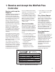
1: Receive and Accept the MinPak Plus Controller Receive and Accept the Shipment The RelianceR Electric MinPak Plus SingleĆPhase DĆC Drive (herein referred to as the Controller) has been designed, manufactured and thoroughly tested to provide many years of reliable service. The shipping container in which you received your Controller has been specifically designed to protect it during transportation and handling. Reliance Terms of Sale, in all instances, are Freight On Board (F.O.B.) point of origin.
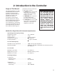
2: Introduction to the Controller Scope of This Manual This manual familiarizes you with the MinPak Plus DĆC Controller. It describes receiving, storage, application, implementation and installation procedures and provides an overview of specifications and operations. Read this manual in its entirety before installing and powering the Controller. Observe all danger notes, warning notes, and caution notes; these precautions point out potentially hazardous procedures and conditions.
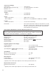
Service Factor Ratings: Service Factor . . . . . . . . . . . . . . . . . . . . . . . . . . . . . 1.0 Continuous Overload Capacity (controller only) . . . . . . . . . . 1.5 of full load rating for one minute Minimum Load . . . . . . . . . . . . . . . . . . . . . . . . . . . . 5% of rated load Service Conditions: Thermal: Chassis . . . . . . . . . . . . . . . . . . . . . . . . . . . . . . . . 55 C Maximum Cabinet . . . . . . . . . . . . . . . . . . . . . . . . . . . . . . . .
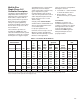
MinPak Plus SingleĆPhase DĆC Controller Description The Reliance Electric MinPak Plus SingleĆPhase DĆC Controller is a fullĆwave power converter without back rectifier, complete with an analog current minor loop and an analog major loop for armature voltage or speed regulation by tachometer feedback. The product line has been setĆup to be sold as listed in Table 2Ć1. The Controller is provided, as standard, in a NEMA Type 4/12 enclosure intended for wall or panel mounting.
Table 2Ć1A.
Table 2Ć1B. Remote Operator Control Stations When Using A MinPak Plus Controller With: Basic Features (Standard Unidirectional Station) NEMA type 4 Station with Basic Features ExplosionĆProof Station with Basic Features Basic Features Plus Armature Reversing (Standard Reversing Station) NEMA Type 4 Station for Reversing ExplosionĆProof Station for Reversing See Table 2Ć2 for Isolation Transformer Specifications and Table 2Ć3 for fuse requirements.
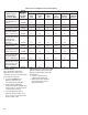
Table 2Ć3. Fuse Requirements. Dual Element Class K5, RK5, 250VAC Fuse HP 1/4Ć3/4 1/2Ć1 1/2 2Ć3 5 1Install AĆC Line Volts 115 230 230 230 Quantity 11 2 2 2 AMP 15 15 30 50 Reliance Part Number 64676Ć1W 64676Ć1W 64676Ć1Z 64676Ć1AD fuse in input line L1 (hot line). Table 2Ć4. Controller Modification Kits.
3: Install and Wire The Drive DANGER DANGER ONLY QUALIFIED ELECTRIĆ CAL PERSONNEL FAMILIAR WITH THE CONSTRUCTION AND OPERATION OF THIS EQUIPMENT AND THE HAZĆ ARDS INVOLVED SHOULD INSTALL, ADJUST, OPERATE AND/OR SERVICE THIS EQUIPMENT. READ AND UNDERSTAND THIS MANUAL IN ITS ENTIRETY BEFORE PROCEEDING. FAILURE TO OBSERVE THIS PRECAUTION COULD RESULT IN SEVERE BODILY INJURY OR LOSS OF LIFE. THIS EQUIPMENT IS AT LINE VOLTAGE WHEN AĆC POWER IS CONNECTED.
1. Verify that the motor is the appropriate rating to use with the controller. 2. Install the DĆC motor in accordance with its own installation instructions. 3. Make sure that coupled applications have proper shaft alignment with the driven machine or that belted applications have proper sheave/belt alignment to minimize unnecessary motor loading.
Install A Disconnect DANGER THIS EQUIPMENT IS AT LINE VOLTAGE WHEN AĆC POWER IS CONNECTED. DISCONĆ NECT AND LOCKOUT ALL UNGROUNDED CONDUCĆ TORS OF THE AĆC POWER LINE. FAILURE TO OBSERVE THESE PRECAUTIONS COULD RESULT IN SEVERE BODILY INJURY OR LOSS OF LIFE. 1. Install a fused disconnect or circuit breaker in the incoming AĆC line. It must accommodate a maximum symmetrical AĆC fault current of 5,000 amperes for controller ratings greater than 1 HP or 1,000 amperes for controller ratings of 1 HP or less.
DANGER THE USER IS RESPONSIBLE FOR CONFORMING TO THE NEC AND ALL OTHER APPLIĆ CABLE LOCAL CODES WITH RESPECT TO WIRING PRACĆ TICES, GROUNDING, DISĆ CONNECTS AND OVERCURĆ RENT PROTECTION ARE OF PARTICULAR IMPORTANCE. FAILURE TO OBSERVE THIS PRECAUTION COULD REĆ SULT IN SEVERE BODILY INJURY OR LOSS OF LIFE. DANGER THIS EQUIPMENT IS AT LINE VOLTAGE WHEN AĆC POWER IS CONNECTED. DISCONĆ NECT AND LOCKOUT ALL UNGROUNDED CONDUCĆ TORS OF THE AĆC POWER LINE.
should be suppressed to reduce noise. Wire AĆC Power to the Controller DANGER THE DRIVE REQUIRES A SINGLEĆPHASE POWER SOURCE OF EITHER 115 VAC OR 230 VAC, 50 OR 60 HZ. IF THE CORRECT VOLTAGE IS NOT AVAILABLE, A TRANSĆ FORMER MUST BE INĆ STALLED BETWEEN THE POWER SOURCE AND THE DRIVE. DO NOT OPERATE THE CONTROLLER WITH AVAILABLE SHORT CIRCUIT CURRENTS IN EXCESS OF 5000 AMPERES. FAILURE TO OBSERVE THESE PRECAUĆ TIONS COULD RESULT IN SEVERE BODILY INJURY OR LOSS OF LIFE. 1.
the Contactor is not supplied by Reliance. contactor coil for dropĆout timing. (See Figure 3.5) Refer to Figure 3.6 and Figure 3.7 for M Contactor connection when ÉÉÉÉÉ ÉÉÉÉÉ ÉÉÉÉÉ ÉÉÉÉÉÉÉÉÉÉ ÉÉÉÉÉÉÉ ÉÉÉÉÉÉÉÉÉÉ ÉÉÉÉÉÉÉ ÉÉÉÉÉÉÉÉÉÉ ÉÉÉÉÉÉÉ NOTE: CLOSED START Switch minimum duration CLOSED STOP Switch FM or RM contactor CLOSED PULL IN DROP OUT PULL IN CR Relay (enables drive) 20 msec 8 msec DROP OUT 30 msec (min) 8 msec Figure 3Ć5.
Control transformer secondary winding 481 482 10 FM 36 RM fd STATIC LOGIC CR 36 approx. 24 VDC MOTOR OVERLOAD 132 STOP START FORWARD RM 38 32 66 39 39 66 38 220 MFD 139 FM 1 220 MFD RUN - Pin Connection - Wire Terminal Board 3:8 FM 35 JOG CR 1 38 65 67 65 REVERSE FM & RM Contactor may not be supplied by Reliance Figure 3Ć7. Reversing Drive Control Circuit.
Wire the DĆC Motor to the Controller 1. Size the motor armature circuit conductors for the specific controller rating and according to applicable codes. 2. Run the DĆC motor armature leads and the shunt field supply leads (if a permanent magnet field motor is not used). See Figure 3Ć8 for the Motor Armature Circuit Connection. Refer to Wire the Field Supply" in this manual for field supply connections. Wire the Field Supply DĆC field supply voltage and maximum field amperes are listed in Table 2Ć1.
BUFFER BOARD B/M 0Ć57005 REGULATOR BOARD B/M 0Ć57101 MAX SPEED (P2) +11.2v OPERATOR'S SPEED REF POT 28 28 MIN SPEED (P1) 5K Common 20 20 126 126 J4 BUFFER 426 LVTU 26 Figure 3Ć10. Reference Circuit for Manual Operator's Speed Reference Circuit. BUFFER BOARD B/M 0Ć57005 REGULATOR BOARD B/M 0Ć57101 MAX SPEED (P2) +11.
BUFFER BOARD B/M 0Ć57005 REGULATOR BOARD B/M 0Ć57101 MAX SPEED (P2) +11.2v OPERATOR'S SPEED REF POT 28 28 MIN SPEED (P1) 5K MANUAL 20 20 126 126 BUFFER AUTO/MANUAL SWITCH 426 26 326 326 Common J4 LVTU AUTO TYPICAL REFERENCE KIT + J1 BUFFER 26 FOLLOWER REFERENCE INPUT - 326 57 Common Figure 3Ć12. Reference Circuit for Follower Reference Kit with the use of the Manual Operator's Reference Option and an Auto/Manual Switch.
This section details the startĆup and adjustment for the basic MinPak Plus Drive as an armature voltage Remove J9 if using Reversing Contactor Place 3Ćwire connector from Auto Reversing Module here. 56 BRN 382 C E G J L N Q 57 S 99 U 71 20 26 28 326 126 26 65 66 39 67 35 38 32 B XFORMER D ORG 139 BLU 61 62 60 AUX.M. K YEL M RED THM 39 PUR Route standard twisted pair I FDBK. to right of the RM Contactor. Remove J7 and J8 if using Torque Taper Kit.
DANGER ONLY QUALIFIED ELECTRIĆ CAL PERSONNEL FAMILIAR WITH THE CONSTRUCTION AND OPERATION OF THIS EQUIPMENT AND THE HAZĆ ARDS INVOLVED SHOULD INSTALL, ADJUST AND/OR SERVICE THIS EQUIPMENT. READ AND UNDERSTAND THIS MANUAL IN ITS ENTIREĆ TY BEFORE PROCEEDING. FAILURE TO OBSERVE THIS PRECAUTION COULD REĆ SULT IN SEVERE BODILY INJURY OR LOSS OF LIFE. DANGER THIS EQUIPMENT IS AT LINE VOLTAGE WHEN AĆC POWER IS CONNECTED. DISCONĆ NECT AND LOCKOUT ALL UNGROUNDED CONDUCĆ TORS OF THE AĆC POWER LINE.
I FDBK. RED 45 ARM. 47 G2 L2 FDBK. G3 47 G4 47 L1 G1 COM MODE SELECTION JUMPER FDBK. C T A 192193 25 15 10 7.5 5 AMPS 3.7 J8 2.5 COM J2 87 86 CURRENT SCALING JUMPER CURRENT SCALING JUMPER CONNECTIONS REGULATION MODE CONNECTIONS Figure 4Ć2. Drive Current Scaling Setup. Regulation Mode Selection The MinPak Plus Drive has three modes of regulation; A = Speed Regulation by Armature Voltage, T = Speed Regulation by Tachometer or C = Counter EMF Feedback.
Table 4Ć2. Control Power Voltages. Function Unregulated +20 VDC Unregulated Ć20 VDC Regulated +11.2 VDC Regulated Ć11.2 VDC Drive SetĆUp Procedure Basic Regulator Maximum Safe Operating Adjustments The following adjustments are available on the Basic Regulator (see Figure 4Ć3): Terminal(s) /Pin(s) 256 271 56 71 Nominal Values (VDC) +20 VDC +5% Ć20 VDC +5% +11.2 VDC +5% Ć11.2 VDC +5% CAUTION: The following adjustĆ ments are maximum safe operĆ ating ranges.
Verify the Correct Direction of Motor Rotation Connect the regulator mode jumper to the A" position. (This initially sets up the drive as a voltage regulator for purposes of start up. Later on you may need to move the jumper to the T" position if your drive is to be speed regulated.) Set the IR COMP" rheostat to zero (fully CCW). If you are going to use a DĆC tachometer, and have the feedback kit installed, it will be necessary to verify that you have the correct polarity of tachometer output.
See Figure 4Ć4 and Figure 4Ć5 for zero speed circuit configurations. Controllers with P/N 57100 regulators that do not have a J10 jumper can achieve zero minimum speed by turning the minimum speed rheostat fully counterĆclockwise. Controllers that have a J10 jumper can achieve zero minimum speed by moving the J10 jumper between K71 and K72, and turning the MIN SPD rheostat fully counterĆclockwise. (See Figure 4Ć5.
Adjusting Maximum Speed 1. Initially set the MAX. SPD. potentiometer on the Regulator Board fully counterĆclockwise. This should prevent the motor from overspeeding with the Operator's Speed Potentiometer set at 100%. 2. Gradually increase the Operator's Speed Potentiometer to 100%. Observe that the motor and drive machine do not exceed their maximum safe speed. 3. Using a suitable screwdriver, adjust the MAX. SPD. potentiometer clockwise until 100% motor speed is obtained.
Table 4Ć3. Initial/Final Adjustment Settings Potentiometers MAX. SPD. MIN. SPD ACC. DEC. I LIMIT IR COMP Jumpers Feedback1 Current Scaling J42 J5, J63 J7, J84 J95 Initial Setting (Factory) Fully CCW (Dot 1) Fully CCW (Dot 1) Fully CCW (Dot 1) Fully CCW (Dot 1) 150% (Dot 7) Fully CCW (Dot 1 = 0%) A 2.5 Final Setting (User) Installed Installed Installed Installed 1> AĆCOM is the standard connection for Armature Feedback; Factory Setting.
5: Troubleshooting General AĆC Line and Power Input DANGER ONLY QUALIFIED ELECTRIĆ CAL PERSONNEL FAMILIAR WITH THE CONSTRUCTION AN OPERATION OF THIS AND THE HAZARDS INVOLVED SHOULD INSTALL, ADJUST, AND/OR SERVICE THIS EQUIPMENT. READ AND UNĆ DERSTAND THIS MANUAL IN ITS ENTIRETY BEFORE PROĆ CEEDING. FAILURE TO OBĆ SERVE THIS PRECAUTION COULD RESULT IN SEVERE BODILY INJURY OR LOSS OF LIFE. This Section details troubleshooting information for the MinPak Plus Single Phase DĆC Drive.
DANGER SOME OF THE FOLLOWING CHECKS AND PROCEDURES REQUIRE THE POWER TO BE ON. EXERCISE EXTREME CARE AS HAZARDOUS VOLTAGE EXISTS. FAILURE TO OBSERVE THIS PRECAUTION COULD RESULT IN SEVERE BODILY INJURY OR LOSS OF LIFE. Start Note #1: Contact local sales/service office. *Ground conditions = 500 KĆOhms or less to ground.
DANGER SOME OF THE FOLLOWING CHECKS AND PROCEDURES REQUIRE THE POWER TO BE ON. EXERCISE EXTREME CARE AS HAZARDOUS VOLTAGE EXISTS. FAILURE TO OBSERVE THIS PRECAUTION COULD RESULT IN SEVERE BODILY INJURY OR LOSS OF LIFE. Start Note #1: Contact local sales/service office. *Ground conditions = 500 KĆOhms or less to ground. Remove AĆC power at disconnect.
DANGER SOME OF THE FOLLOWING CHECKS AND PROCEDURES REQUIRE THE POWER TO BE ON. EXERCISE EXTREME CARE AS HAZARDOUS VOLTAGE EXISTS. FAILURE TO OBSERVE THIS PRECAUTION COULD RESULT IN SEVERE BODILY INJURY OR LOSS OF LIFE. Start Note #1: Contact local sales/service office. Apply AĆC Power and check for proper line voltage between terminals 51 and 52. Do you have correct voltage ? No Do you have an open circuit ? Check for open fuses/disconnect Yes No Yes Problem is with AĆC line voltage supply.
! ! # ! " " 3B Is there a Yes thermostat/jumper wired there? Remove power from drive and check for cotinuity between terminals 32 and 132. Thermostat or jumper is malfunctioning, corĆ rect the problem. No Is there continuity? Check for a motor therĆ mostat or a jumper wired to terminals 32 and132.
DANGER SOME OF THE FOLLOWING CHECKS AND PROCEDURES REQUIRE THE POWER TO BE ON. EXERCISE EXTREME CARE AS HAZARDOUS VOLTAGE EXISTS. FAILURE TO OBSERVE THIS PRECAUTION COULD RESULT IN SEVERE BODILY INJURY OR LOSS OF LIFE. Start Note: #1: Contact local sales/service office. *Reference the layout of the regulator board for PIN location. **The center arm switch should go to PIN 35 and the run position of the switch should connect to the common point between the start/stop pushbutton.
DANGER SOME OF THE FOLLOWING CHECKS AND PROCEDURES REQUIRE THE POWER TO BE ON. EXERCISE EXTREME CARE AS HAZARDOUS VOLTAGE EXISTS. FAILURE TO OBSERVE THIS PRECAUTION COULD RESULT IN SEVERE BODILY INJURY OR LOSS OF LIFE. Start Note #1: Contact local sales/service office. Check for speed reference 0 to 8 VDC between terminals 126 and 57 (common). Is reference voltage present? Check DĆC Bus voltage 0 to 90, or 180 VDC between terminals 47 and 45.
DANGER SOME OF THE FOLLOWING CHECKS AND PROCEDURES REQUIRE THE POWER TO BE ON. EXERCISE EXTREME CARE AS HAZARDOUS VOLTAGE EXISTS. FAILURE TO OBSERVE THIS PRECAUTION COULD RESULT IN SEVERE BODILY INJURY OR LOSS OF LIFE. A From previous page From previous page B Is voltage present? Note #1: Contact local sales/service office.
DANGER SOME OF THE FOLLOWING CHECKS AND PROCEDURES REQUIRE THE POWER TO BE ON. EXERCISE EXTREME CARE AS HAZARDOUS VOLTAGE EXISTS. FAILURE TO OBSERVE THIS PRECAUTION COULD RESULT IN SEVERE BODILY INJURY OR LOSS OF LIFE. Note #1: Contact local sales/service office. *Install a jumper between terminal 26 and 126. From previous page C Has jumper been cut or removed? Yes * Correct the problem Fixed? Yes Done No No See Note #1 Replace Regulator Board Fixed? Yes Done No See Note #1 Figure 5Ć8.
DANGER SOME OF THE FOLLOWING CHECKS AND PROCEDURES REQUIRE THE POWER TO BE ON. EXERCISE EXTREME CARE AS HAZARDOUS VOLTAGE EXISTS. FAILURE TO OBSERVE THIS PRECAUTION COULD RESULT IN SEVERE BODILY INJURY OR LOSS OF LIFE. D From previous 2 pages Note #1: Contact local sales/service office.
DANGER THE FOLLOWING CHECKS AND PROCEDURES REQUIRE THE POWER TO BE ON. EXERCISE EXTREME CAUTION AS HAZARDOUS VOLTAGE EXISTS. FAILURE TO OBSERVE THIS PRECAUTION COULD RESULT IN SEVERE BODILY INJURY OR LOSS OF LIFE. Note: #1: Contact local sales/service office. Start If using TACH feedback, change feedback selection jumper to the A" position for armature voltage feedback and restart the drive.
1) Part Number 701819-9X has been replaced by 701819-303AW. Rockwell Automation, Inc.
//'.&*4 3*%+ '('0'.
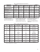
Table AĆ1. Controller Model Numbers (3) Enclosed Chassis 14C10 14C20 14C11 14C21 14C12 14C22 14C13 14C23 Transf. KVA Optional Model Number HP 1/4 1/3 1/2 3/4 1/2 3/4 1 1 1/2 2 3 5 VAC 115 115 115 115 230 230 230 230 230 230 230 AĆC Amps (RMS) 3.5 5.2 7.0 10.5 3.5 5.2 7.0 10.5 14.0 21.0 35.0 DĆC Arm. (Volts) 90 90 90 90 180 180 180 180 180 180 180 1Standard 2Maximum permissible available symmetrical RMS fault current 3Does not include current required for Field Supply (if used). DĆC Arm.
Table AĆ2.
Table AĆ4. Isolation Transformer Specifications (Continued). HP kVA Primary Vac 2 5.0 3Ć5 10.0 230/460 575 230/460 575 Secondary Vac 230 230 230 230 Reliance Part Number 77530Ć16G 77530Ć17G 77530Ć16H 77530Ć17H NOTE: Smaller drives through 3/4 HP @ 115 VAC and 2.0 HP @ 230 VAC may be used with permanent magnetic field motors, and those drive models are supplied without a DĆC field supply. Table AĆ5. Fuse Requirements.
Figure AĆ6.
ÉÉÉÉÉ ÉÉÉÉÉ ÉÉÉÉÉ ÉÉÉÉÉÉÉÉÉÉ ÉÉÉÉÉÉÉ ÉÉÉÉÉÉÉÉÉÉ ÉÉÉÉÉÉÉ ÉÉÉÉÉÉÉÉÉÉ ÉÉÉÉÉÉÉ : CLOSED START Switch CLOSED STOP Switch FM or RM contactor CLOSED PULL IN DROP OUT PULL IN CR Relay (enables drive) 20 msec 8 msec DROP OUT 30 msec (min) 8 msec Figure AĆ8. Armature Contactor Sequencing and Regulator Start/Stop Timing. Control transformer secondary winding 481 482 10 FM 36 fd STATIC LOGIC CR FM 65 38 approx.
Control transformer secondary winding 481 482 10 FM 36 RM fd STATIC LOGIC CR 36 approx. 24 VDC MOTOR OVERLOAD 132 STOP START FORWARD RM 38 32 66 39 39 66 38 220 MFD 139 FM 1 220 MFD RUN - Pin Connection - Wire Terminal Board NOTE: FM 35 JOG 67 65 38 CR 1 65 REVERSE FM & RM Contactor may not be supplied by Reliance Figure AĆ10. Reversing Drive Control Circuit.
BUFFER BOARD B/M 0Ć57005 REGULATOR BOARD B/M 0Ć57101 MAX SPEED (P2) +11.2v OPERATOR'S SPEED REF POT 28 28 MIN SPEED (P1) 5K Common 20 20 126 126 BUFFER 426 J4 LVTU 26 Figure AĆ12. Reference Circuit for Manual Operator's Speed Reference Circuit. BUFFER BOARD B/M 0Ć57005 REGULATOR BOARD B/M 0Ć57101 MAX SPEED (P2) +11.
BUFFER BOARD B/M 0Ć57005 REGULATOR BOARD B/M 0Ć57101 MAX SPEED (P2) +11.2v OPERATOR'S SPEED REF POT 28 28 MIN SPEED (P1) 5K MANUAL 20 20 126 126 BUFFER AUTO/MANUAL SWITCH 426 26 326 326 Common J4 LVTU AUTO TYPICAL REFERENCE KIT + J1 BUFFER 26 FOLLOWER REFERENCE INPUT - 326 57 Common Figure AĆ14. Reference Circuit for Follower Reference Kit with the use of the Manual Operator's Reference Option and an Auto/Manual Switch.
Remove J9 if using Reversing Contactor Place 3Ćwire connector from Auto Reversing Module here. 56 BRN 382 C E G J L N Q 57 S 99 U 71 20 26 28 326 126 26 65 66 39 67 35 38 32 B XFORMER D ORG 139 BLU 61 62 60 AUX.M. K YEL 66 REV. FWD. M RED THM 39 PUR Remove J7 and J8 if using Torque Taper Kit. YEL J9 47 G2 L2 FDBK. G3 47 G4 47 192193 L1 G1 COM J5 40 AUTO REV I FDBK. RED 45 ARM. 32 F Route standard twisted pair I FDBK. to right of the RM Contactor.
Table AĆ8. Control Power Voltages. Terminal(s) /Pin(s) 256 271 56 71 Function Unregulated +20 VDC Unregulated Ć20 VDC Regulated +11.2 VDC Regulated Ć11.2 VDC Nominal Values (VDC) +20 VDC +5% Ć20 VDC +5% +11.2 VDC +5% Ć11.2 VDC +5% I FDBK. RED 45 ARM. 47 G2 L2 FDBK. G3 47 G4 47 L1 G1 COM MODE SELECTION JUMPER FDBK. C T A 192193 25 15 10 7.5 5 AMPS 3.7 J8 2.5 COM J2 REGULATION MODE CONNECTIONS Figure AĆ16. Drive Current Scaling Setup.
J8 3.7 COM 2.5 FDBK. C T A J7 319 0 MAX. SPD. 219 56 CLIP FOR 85 50HZ 57 0 MIN. SPD. 87 86 ACCEL. SPD. 17 0 DECEL. SPD.
%" ' " % ! "" $ ' $ %#$ $ $$ # $ $ $ "# MAX. SPD. MIN. SPD ACC. DEC. I LIMIT IR COMP % ! "# Feedback1 Current Scaling J42 J5, J63 J7, J84 J95 $ $$ $ "& Fully CCW (Dot 1) Fully CCW (Dot 1) Fully CCW (Dot 1) Fully CCW (Dot 1) 150% (Dot 7) Fully CCW (Dot 1 = 0%) A 2.5 $$ # " Installed Installed Installed Installed 1> AĆCOM is the standard connection for Armature Feedback; Factory Setting.
A:17 Figure AĆ20. Controller Schematic.
A:18 Figure AĆ21. Controller Technical Data.
B: GLOSSARY OF TERMS Altitude: The atmospheric altitude (height above sea level) at which the motor or controller will be operating. Armature: The portion of the DĆC motor which rotates. Rated Full Load Current: Armature current in amperes. Armature Resistance: Measured in ohms at 25 degrees Celsius (cold). Base Speed: The speed which a DĆC motor develops at rated armature and field voltage with rated load applied. Chassis Ground: Any electrical connection to the metal body of the controller.
NEMA Definitions: NEMA Type 4 is generally defined as an indoor/outdoor enclosure that is watertight and dustĆtight. It is designed to protect against splashing and hoseĆdirected water within specific test limitations. NEMA Type 12 is generally defined as an indoor enclosure that is dustĆtight and oilĆtight. It is designed to resist fibers, filings, dust, dirt and light oil splashing. RPM: Revolutions per Minute Ć The number of times per minute the shaft of the motor (machine) rotates.
Appendix C: Theory Of Operation This is a generalized theory of operation for the MinPak Plus controller. It covers internal components and their functions. It also explains the relationship of the drive motor and the controller. Motor - A Reliance Super RPM wound field DĆC motor is compatible for use with the MinPak Plus controller. The Super RPM allows adjustable speed service as a straight shunt machine.
The relative timing of the gate pulse with respect to the AĆC plant supply will determine the conduction angle - that is, relative conduction time - of the thyristor and of the bridge. Thus the average DĆC output voltage from the bridge to the motor armature is controlled. Firing the thyristor gates early in the positive halfĆcycle of the incoming sinusoid allows it to conduct for a relatively long time until commutated off by the line.
All electrical connections to the Regulator Module are made with tinĆplated pin connectors. The input/output arrangement of these pins is intended to physically isolate the different circuits, thereby minimizing electrical noise coupling. All optional external voltage signals which may contain electrical noise are fed through filtering and isolation circuits to entering the Regulator Module. Thus reliable operation is assured even in a noiseĆpolluted industrial environment.
AĆC Line and Power Input 5:1 Adjusting Minimum Speed 4:5 Adjusting Maximum Speed 4:7 Basic Regulator Maximum Safe Operating Adjustment 4:4 Motor Ground Check 4:2 Optional Kits 5:1 Power Off Inspection 4:2 Power On 4:3 Controller Mounting Dimensions 3:2 Current Limit 4:7 DĆC Motor 5:1 Determination of Tachometer Output Polarity 4:5 Drive Deceleration Time 4:7 Drive Acceleration Time 4:7 Drive Identification Nameplate 1:1 Drive SetĆup Procedure 4:4 Receive and Accept the FlexPak Cont
U.S. Drives Technical Support Tel: (1) 262.512.8176, Fax: (1) 262.512.2222, Email: support@drives.ra.rockwell.com, Online: www.ab.com/support/abdrives Trademarks not belonging to Rockwell Automation are property of their respective companies. Publication D-3838-6 – June 1994 Copyright © 1994 Rockwell Automation, Inc. All Rights Reserved. Printed in USA.