Triguard SC300E MDO32BNS 32-Channel Digital Output Module (MDO32BNS) Issue 7 October 2005 The Digital Output Module provides the output control interface between the SC300E processing environment and up to 32 common low voltage field devices. All field outputs from the module are galvanically isolated from the system.
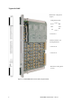
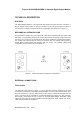
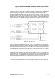
Triguard SC300E Mechanical coding block (Upper) Configuration Links Link 3 ICCB HW HLV GTZ 320 321 Link 1 Connector J1 Common Interface (CI) (on daughterboard) Connector J2 Connector J3 Mechanical coding block (Lower) Figure 1-1.
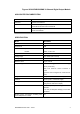
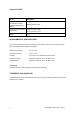
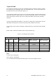
Triguard SC300E MDO32BNS 32-Channel Digital Output Module ASSOCIATED DOCUMENTATION Reference No Title 008-5097 Chassis User Manual 008-5135 TDO16AIN Digital Output Termination Card, DIN to Screw Terminal Introduced Power User Manual 008-5179 TDO16BIN Digital Output Termination Card DIN to DIN, Introduced Power User Manual SPECIFICATION Model MDO32BNS Channels 32 Architecture TMR Indicators: Input: One per channel Module: Health, 3 x On Line Output driver FED Voltage range 18 to 30Vdc (
Triguard SC300E Model MDO32BNS Module power consumption including field power dissipation in module 19W @ minimum load Overall size (mm) Overall size (inches) 400(9U)H x 397L x 28W Weight 1.8kg 59W @ maximum load 15.75H x 15.63L x 1.1W ENVIRONMENTAL SPECIFICATION The maximum ambient temperature measured at the hottest point within the Triguard system shall not be greater than 60 degrees centigrade.
Triguard SC300E MDO32BNS 32-Channel Digital Output Module TECHNICAL DESCRIPTION PHYSICAL The Digital Output Module is a 9U high PCB with integral front panel and rear connectors; a plug-in daughter board carries the Common Interface circuits.
Triguard SC300E 6 MDO32BNS October 2005 – Issue 7
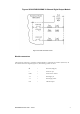
Triguard SC300E MDO32BNS 32-Channel Digital Output Module Figure 2-2. Basic field load circuit Module connectors The System bus connector is J1 and the Common Interface is connected via J4 and J5 (not shown).
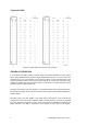
Triguard SC300E Figure 2-3. Field output connectors J2 and J3 pinouts THEORY OF OPERATION In accordance with TMR practice, channel output command information from the system follows three identical paths through the Digital Output Module (Figure 2-4) each path at the command of its own microcontroller in the Common Interface. As the switching speed of the module exceeds the system scan rate the channel data can be converted to serial form before entering the module from the Common Interface.
Triguard SC300E MDO32BNS 32-Channel Digital Output Module The output switch for each channel comprises six FETs connected in the series/parallel network shown and providing 2 out of 3 majority voting between the three paths A, B and C. A front panel LED at the switch output is lit when the switch is closed.
Triguard SC300E The module uses hardware circuitry and configuration links that enable the system to identify the module type and configuration mode. The configuration links 1, 2 and 3 are located in the top right-hand corner of the module (see Figure 1.1). Link 1 allows the module to be set up for 321 or 320 mode operation. 320 mode means that the system will continue to function with two out of three serviceable circuits.
Triguard SC300E MDO32BNS 32-Channel Digital Output Module MDO32BNS October 2005 – Issue 7 11
Triguard SC300E 12 MDO32BNS October 2005 – Issue 7
Triguard SC300E MDO32BNS 32-Channel Digital Output Module COMMON INTERFACE The three discrete control circuits in the Common Interface (A, B, and C) (Figure 2-6) are each responsible for the control of the corresponding one third of the I/O module circuits. Each control circuit comprises a microcontroller with a dedicated watchdog, data buffers and shared RAM. The circuit is powered via the module and permits live insertion of replacement modules.
Triguard SC300E Figure 2-6.
Triguard SC300E MDO32BNS 32-Channel Digital Output Module SERVICING SCOPE System repair is by module replacement. Faulty modules are not repairable in the field; they should be replaced by new modules and returned for repair. CAUTION 1 The module contains components that may be electrostatically sensitive. It should be transported and stored in its original packaging material. CAUTION 2 Before fitting a new module ensure that the setting of all three links is the same as that on the old module.
Triguard SC300E Removal and replacement CAUTION 3 Failure to take the faulty module off-line before removing it from the chassis could trigger a fault alarm or cause plant shutdown . CAUTION 4 When inserting a module ensure that it is aligned with the markings on the chassis rails and that it engages with the upper and lower guides. Improper insertion may cause damage to the module and/or chassis connectors.
Triguard SC300E MDO32BNS 32-Channel Digital Output Module Dual-slot hot repair Insert the new module into the vacant hot repair slot ensuring that it engages properly in the upper and lower guides in the chassis, the top and bottom chassis rails carry alignment marks to assist. Pull out the black ejection levers and as the module is pushed back engage the levers on the chassis rails.
Triguard SC300E PREVENTIVE MAINTENANCE No preventive maintenance is necessary. SERVICE SUPPORT Spare parts and technical advice can be obtained from your local area office.