Triguard SC300E MDO16GNS 16-Channel Digital Output Module 48Vdc (MDO16GNS) Issue 2 October 2005 INTRODUCTION PURPOSE The 48Vdc Digital Output Module MDO16GNS provides the output control interface between the SC300E processing environment and up to 16 field items. All field outputs from the module are galvanically isolated from the system.
Triguard SC300E 2 MDO16GNS October 2005 – Issue 2
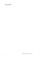
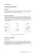
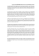
Triguard SC300E MDO16GNS 16-Channel D/O Module 48Vdc Mechanical coding block (Upper) ConfigurationLinks Link3 HW ICC B GTZ HL V 320 321 Link 1 Connector J1 Common Interface (CI) Module Connector J2 Connector J3 Mechanical coding block (Lower) Figure 1-1 General view and front panel detail MDO16GNS October 2005 – Issue 2 3
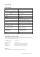
Triguard SC300E SPECIFICATION Model MDO16GNS Channels 16 Architecture TMR Indicators: One per point Health, 3 x On Line Input Modules Output driver FET Voltage range 48Vdc ±10% Voltage drop Less than 3V Maximum drive Resistive load: 1A per channel Tungsten load: 0.
Triguard SC300E MDO16GNS 16-Channel D/O Module 48Vdc TRANSPORT AND HANDLING The MDO16GNS must be transported and stored in its original packing material which should be retained for this purpose.
Triguard SC300E TECHNICAL DESCRIPTION PHYSICAL The MDO16GNS is a 9U high module with integral front panel and rear connectors. A daughterboard carries the common interface circuits. Figure 1-1 shows the general layout, including the location of the connectors and front panel details. Mechanical coding blocks All Input/Output modules carry two coder blocks equipped with pins which mate with holes in corresponding blocks in the chassis and prevent the module being inserted into the wrong slot.
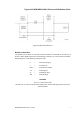
Triguard SC300E MDO16GNS 16-Channel D/O Module 48Vdc Figure 2-2 Basic field load circuit Module connectors The system bus connector is J1 and the common interface is connected via J4 and J5 (not shown). All the digital outputs are routed through connector J2.
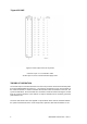
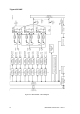
Triguard SC300E Figure 2-3 Field output connector J2 pinouts Connector J3 pin 1c is connected to earth. All other pins on J3 are connected to field supply return. THEORY OF OPERATION The channel output command information from the main processor follows three identical paths through the MDO16GNS (see Figure 2-4 ), each path is controlled by its own microcontroller in the common interface.
Triguard SC300E MDO16GNS 16-Channel D/O Module 48Vdc The data streams are then applied to the 16-bit output shift registers. The serial bits are clocked successively into the shift registers until the 16th bit has been received. The registers then latch the data and present it on the 16-bit busses (CHANA, CHANB and CHANC) to the output switches. The data is continuously refreshed in this manner and updated at each scan of the SC300E system.
DC Triguard SC300E Figure 2-4.
Triguard SC300E MDO16GNS 16-Channel D/O Module 48Vdc Common Interface The three discrete control circuits in the common interface (A, B, and C) are each responsible for the control of the corresponding one third of the I/O module circuits. Each control circuit comprises a microcontroller with a dedicated watchdog, data buffers and shared RAM. The circuit is powered via the module and permits live insertion of replacement modules.
Triguard SC300E Figure 2-5 Common interface - Block diagram 12 MDO16GNS October 2005 – Issue 2
Triguard SC300E MDO16GNS 16-Channel D/O Module 48Vdc SERVICING SCOPE Repair is by module replacement. Faulty modules are not repairable in the field. They should be replaced by new modules and returned for repair. CAUTION 1 Before fitting a new module ensure that the setting of the configuration links are the same as that on the old module. CAUTION 2 This module contains components that may be electrostatically sensitive. It should be transported and stored in its original packaging material.
Triguard SC300E When inserting a module ensure that it is aligned with the markings on the chassis rails and that it engages with the top and bottom guides. Improper insertion may cause damage to the module and/or chassis connectors.
Triguard SC300E MDO16GNS 16-Channel D/O Module 48Vdc SINGLE-SLOT HOT REPAIR 1. Operate the On/Off Line Request switch on the faulty module. The three On Line LEDs should all extinguish to indicate that the main processors have recognised the request and taken the module off-line. The last read data input from the module will be maintained until the new module is on-line. 2. Slacken the two module securing screws and use the black ejection levers (top and bottom) to draw the module from its slot. 3.
Triguard SC300E SERVICE SUPPORT SPARES Spare parts and technical advice can be obtained from your local area offices.