Triguard SC300E MDO16FNS 16-Channel Digital Output Module 120Vac/dc (MDO16FNS) Issue 4 October 2005 INTRODUCTION PURPOSE The 120Vac/dc Digital Output Module MDO16FNS provides the output control interface between the SC300E processing environment and up to 16 high-voltage field items. All field outputs from the module are galvanically isolated from the system.
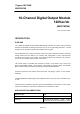
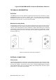
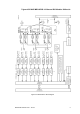
Triguard SC300E Terminals, Internally Powered, High Voltage User Manual Mechanical coding block (Upper) Connector J1 Common Interface (CI) Module Connector J2 Connector J3 Protective Cover Mechanical coding block (Lower) Figure 1-1 General view and front panel detail 2 MDO16FNS October 2005 – Issue 4
Triguard SC300E MDO16FNS 16-Channel D/O Module 120Vac/dc SPECIFICATION Model MDO16FNS Channels 16 Architecture TMR Indicators: One per point Health, 3 x On Line Input Modules Output driver FET Voltage range 99 to 132Vac/dc Voltage drop Less than 4V Maximum drive Resistive load: 0.50A per channel Tungsten load: 0.
Triguard SC300E TRANSPORT AND HANDLING The MDO16FNS must be transported and stored in its original packing material which should be retained for this purpose.
Triguard SC300E MDO16FNS 16-Channel D/O Module 120Vac/dc TECHNICAL DESCRIPTION PHYSICAL The MDO16FNS is a 9U high PCB with integral front panel and rear connectors. A plug-in daughterboard carries the common interface circuits. The board faces are protected by detachable covers (see Section 3.1, Scope). Figure 1-1 shows the general layout, including the location of the connectors, covers and front panel details.
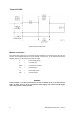
Triguard SC300E Figure 2-2 Basic field load circuit Module connectors The system bus connector is J1 and the common interface is connected via J4 and J5 (not shown). All the digital outputs are routed through connector J2.
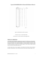
Triguard SC300E MDO16FNS 16-Channel D/O Module 120Vac/dc Figure 2-3 Field output connector J2 pinouts Connector J3 pin 1c is connected to earth. All other pins on J3 are connected to field supply return. THEORY OF OPERATION In accordance with TMR practice, channel output command information from the MPP follows three identical paths through the MDO16FNS (see Figure 2-4 ), each path at the command of its own microcontroller in the common interface.
Triguard SC300E The data streams are then applied to the 16-bit output shift registers. The serial bits are clocked successively into the shift registers until the 16th bit has been received. The registers then latch the data and present it on the 16-bit busses (CHANA, CHANB and CHANC) to the output switches. The data is continuously refreshed in this manner and updated at each scan of the SC300E system.
Triguard SC300E MDO16FNS 16-Channel D/O Module 120Vac/dc Figure 2-4 MDO16FNS - Block diagram MDO16FNS October 2005 – Issue 4 9
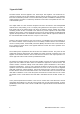
Triguard SC300E Common Interface The three discrete control circuits in the common interface (A, B, and C) are each responsible for the control of the corresponding one third of the I/O module circuits. Each control circuit comprises a microcontroller with a dedicated watchdog, data buffers and shared RAM. The circuit is powered via the module and permits live insertion of replacement modules.
Triguard SC300E MDO16FNS 16-Channel D/O Module 120Vac/dc Figure 2-5 Common interface - Block diagram System Configuration The Digital Output module requires adequate ventilation to operate at its full capacity. For convection cooled systems the output module should be fitted in the lowest module chassis and the hot repair partner slot should not be occupied. When forced air cooling is applied to a system these limitations are removed.
Triguard SC300E SERVICING SCOPE Repair is by module replacement. Faulty modules are not repairable in the field. They should be replaced by new modules and returned for repair. WARNING Lethal voltages are present in this equipment. The protective covers are to prevent access to circuits. There are no user-serviceable components under the covers For your safety: Do not remove the covers.
Triguard SC300E MDO16FNS 16-Channel D/O Module 120Vac/dc Where there is a hot repair partner allocation, use the ‘Dual-slot hot repair’ procedure, otherwise use the ‘Single-slot hot repair’ procedure.
Triguard SC300E CONFIGURATION Before fitting a new module ensure that 321/320 link setting is the same as that on the old module. REMOVAL AND REPLACEMENT CAUTION 3 Failure to take the faulty module off-line before removing it from the chassis could trigger a fault alarm or cause plant shutdown. CAUTION 4 When inserting a module ensure that it is aligned with the markings on the chassis rails and that it engages with the top and bottom guides.
Triguard SC300E MDO16FNS 16-Channel D/O Module 120Vac/dc DUAL-SLOT HOT REPAIR 1. Insert the new module into the vacant hot repair slot ensuring that it engages properly in the upper and lower guides in the chassis. The top and bottom chassis rails carry alignment marks to assist. Pull out the ejection levers and as the module is pushed back engage the levers on the chassis rails. The levers should then be used to draw the module into position, some resistance will be felt as the rear connector pins engage.